NTC Thermistor Sensors in the up to 80 °c band. Comfort and condensation control: seat heating, mirror demisting, enclosure anti-condensation, battery pre-conditioning. Almost any construction reaches it, so the choice is decided by cost and thickness rather than by the temperature. The construction is rated 200 °C continuous, so this band sits inside its ceiling — and where a band sits relative to the ceiling is the whole of the selection argument.
What the Up to 80 °C Band Requires
Comfort and condensation control: seat heating, mirror demisting, enclosure anti-condensation, battery pre-conditioning. Almost any construction reaches it, so the choice is decided by cost and thickness rather than by the temperature.
| Band | Up to 80 °C |
|---|---|
| This construction, continuous | 200 °C |
The band sits comfortably inside the 200 °C ceiling, which is where a heater should be specified: the margin between the working temperature and the insulation limit is what absorbs a poor thermal path, a warm ambient and a control overshoot without shortening the life of the part.
Why the Boundary Is Where It Is
80 °C is not a material boundary at all — every construction here passes through it — so the choice inside this band is decided by cost, thickness and area rather than by temperature. That is why printed film competes here and nowhere above it.
The engineering in this band is uniformity and control, not survival: comfort heating, condensation control and battery pre-conditioning all care about holding a few degrees evenly over a large area, which is a watt density and layout problem.
What an NTC Thermistor Sensors Is
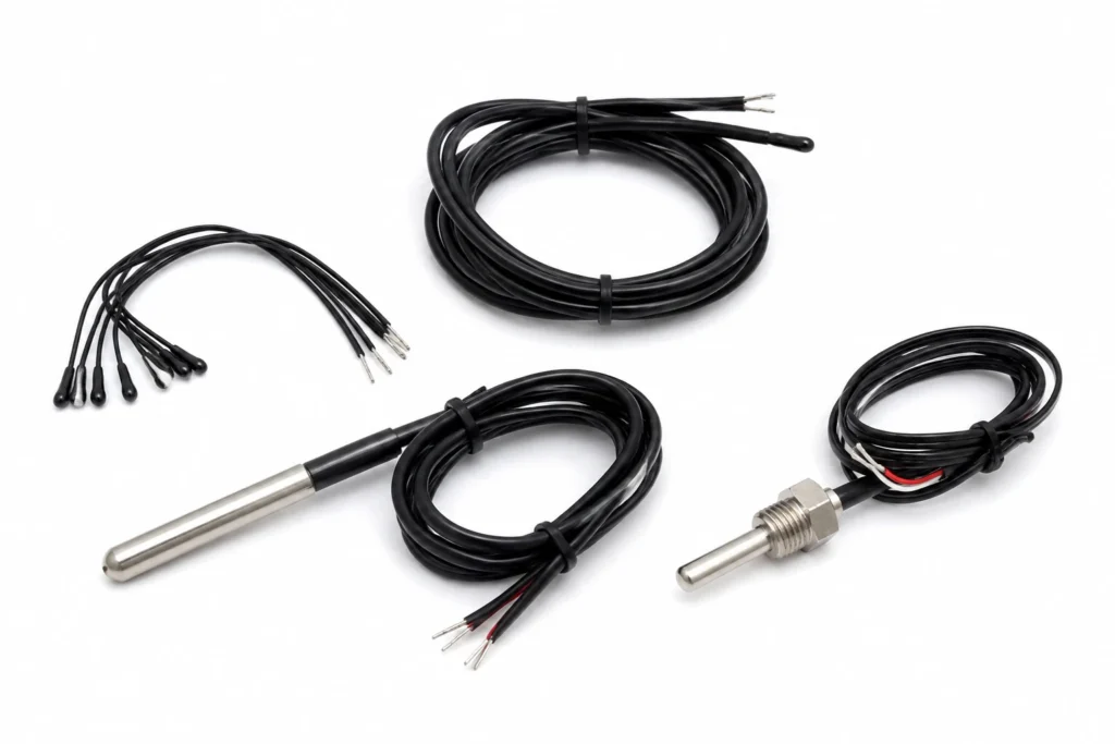
The 10K B3950 thermistor is the default sensor on a low voltage heater: cheap, sensitive, and readable by any microcontroller with one resistor.
A sensing component, specified by its tolerance class, its usable range and its response time. It has no watt density and no outline; it is fitted to a heater or to the surface the heater is warming, and where it is fitted decides what the control loop is actually controlling.
The heat leaves through whatever the component is clamped or bonded to; a sensing component adds no heat of its own and simply has to be in thermal contact with the thing it is reporting on.
| Total thickness | Component |
|---|---|
| Maximum size, one piece | Component |
| Continuous working temperature | 200 °C |
The continuous limit of 200 °C is set by the insulation system. The element alloy would run far hotter; it is never the element that decides.
Which Temperature Is Being Held
Three temperatures matter and they are not the same number: the element temperature, the temperature of the surface being heated, and the ambient. A heater rated for a continuous working temperature is rated at the element — the hottest point in the assembly, and the one nothing on the outside is measuring.
The gap between element and surface is the thermal path. Bonded to metal it may be a few degrees; across an air gap, a void in the adhesive or a dry clamped joint it can be tens of degrees, and every one of them appears at the element rather than at the load.
Attachment and Thermal Contact
A sensing component is fitted where it will read the temperature that matters: against the element for a limit device, against the load for a control device. The two positions give different numbers, and choosing the wrong one is the commonest reason a correctly built loop holds the wrong temperature.
A sensor reads its own junction, not the surface it is near. Bed it in thermal compound, clamp it, or pot it into the assembly: an air gap of a tenth of a millimetre between a thermistor and the plate it is supposed to be measuring is worth several degrees of error, and it is an error the controller cannot see.
Control and Protection
This heater has no way of limiting its own temperature. Resistance heating draws roughly the same power whatever the temperature, so with the load removed, the fluid gone, the fan stopped or the sensor open circuit, the element keeps producing watts until something stops it.
The design must therefore contain a control device and, separately, a protective one: a controller with a sensor to hold the set point, and a bimetal thermostat or a one-shot thermal cutoff wired in series with the element to open the circuit if the loop ever fails. The two are not interchangeable — a controller that has lost its sensor cannot protect anything, which is exactly the fault the cutoff exists for.
How This Construction Fails
- Loss of the control loop. An open-circuit sensor, a welded relay contact or a controller in manual leaves the element at full power with nothing watching it — the case the series thermal cutoff exists for, and the reason it must not be omitted to save a part.
- Measuring the wrong thing. A sensor in the air near a heated plate reports the air, and the loop holds the air where the specification wanted the plate. Nothing in the instrument can detect this.
Where This Construction Is the Wrong Answer
- Do not plan on running above 200 °C. That ceiling belongs to the insulation system, not to the element alloy, and it is not a figure that derating extends — past it the insulation degrades and the dielectric strength goes with it.
- Do not rate this component as though it were the heater. It carries a contact rating or a tolerance class; the heater next to it decides the power, the watt density and the temperature the assembly reaches.
How to Specify One
This is a made-to-drawing part, so there is no catalogue number to quote. A quotation is built from the following, and the more of it that arrives with the enquiry the fewer rounds it takes:
- The temperature to be sensed or switched, and the tolerance the application actually needs.
- Where the component sits — against the element, in the potting, on the load, or in the airflow.
- The electrical duty: for a switching device, the voltage, the current and whether the load is AC or DC.
- Lead length, insulation and termination, and whether the component is fitted by us into a heater assembly or supplied loose.
- The standard the end product is certified to, so the component chosen is one that fits inside that approval.
Lead time: Samples 7-10 days from approved drawing; production 15-20 days.
NTC Thermistor Sensors — Capability Table
These are process limits for the construction, not the specification of one stocked item. Every line is what the factory can hold; what your part holds is fixed on your drawing.
| Parameter | Specification | Limit / note |
|---|---|---|
| Type | Negative temperature coefficient thermistor | Resistance falls as temperature rises, steeply |
| Standard part | 10 ku03a9 at 25 u00b0C, B25/50 = 3950 K | The value nearly every controller expects by default |
| Other values | 5 ku03a9, 50 ku03a9, 100 ku03a9; B values 3435 K to 4100 K | Chosen to match the controller, not the heater |
| Tolerance | u00b11% resistance, u00b11% B value | u00b10.5 u00b0C interchangeable parts available |
| Temperature range | -40 u00b0C to +200 u00b0C depending on encapsulation | Epoxy bead to +125 u00b0C, glass bead to +200 u00b0C |
| Response time | 1 to 10 seconds depending on mass and mounting | Mounting dominates: a sensor in air reads air |
| Encapsulation | Epoxy bead, glass bead, or laminated into the heater | Laminated is what makes it read the element |
| Leads | PTFE or silicone insulated, to your length and termination |
Figures are the published tolerance and rating bands of the standard sensor and control components fitted to these heaters. Sensor tolerance classes follow IEC 60751 for RTDs and IEC 60584 for thermocouples; thermostat and thermal cutoff ratings are the component manufacturers' own.