
Design
Element layout from your outline, voltage and target temperature — conductor gauge, path length and pitch calculated before any tooling is cut.
We build heating elements to customer drawings for equipment manufacturers, instrument builders, battery and vehicle programmes, and industrial projects worldwide. Nothing here comes off a shelf, which is why this site publishes process capability instead of a size list.
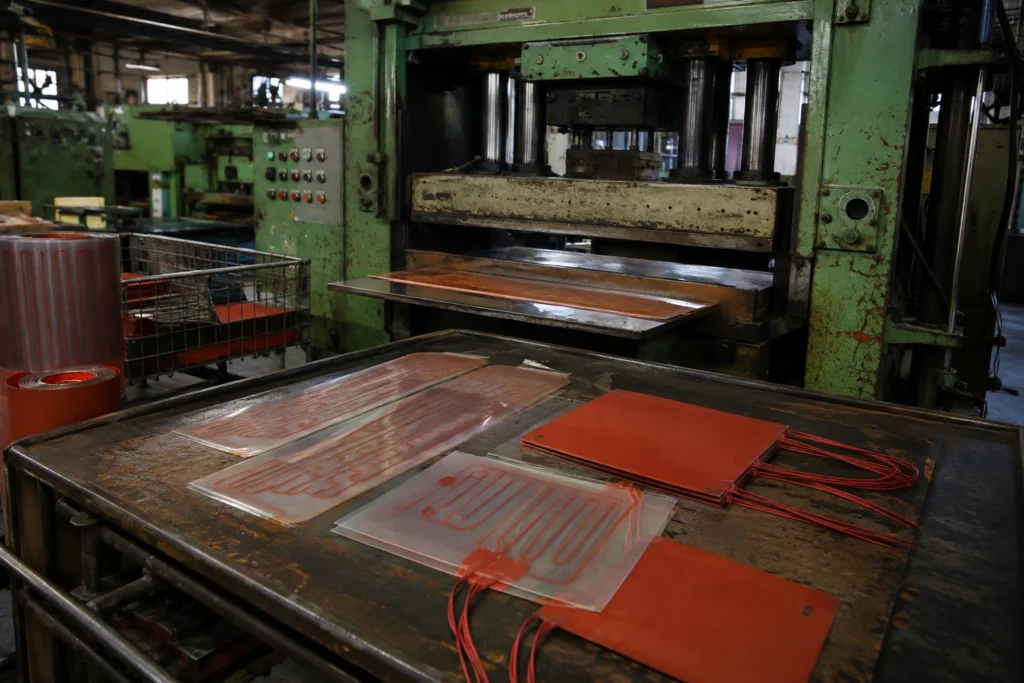
Our factory builds silicone rubber heaters, polyimide and PET film heaters, thick film heaters on stainless and ceramic substrates, PTC assemblies and epoxy heating plates, together with the thermostats, sensors and controllers that make a heated product safe. Production is organised around the two things that decide whether a heater lasts: the watt density it is designed at, and the integrity of the insulation around the element.
Circuit layout, element winding and etching, lamination and potting, die cutting, lead termination, electrical test and thermal imaging all happen here. Every unit is measured for resistance, held at its dielectric test voltage and measured again for insulation resistance before it leaves; sample units from each lot are run under power and imaged, because a hot spot is invisible to a meter and obvious to a camera.
Element layout from your outline, voltage and target temperature — conductor gauge, path length and pitch calculated before any tooling is cut.
Silicone rubber, polyimide, PET, fired glass dielectric, filled epoxy and PTC ceramic — chosen for the temperature and the environment, since that choice is the temperature limit.
Thermostats, thermal cutoffs, NTC, PT100 and thermocouples built in under the same insulation and tested as one assembly.
Resistance, dielectric withstand and insulation resistance on every unit; thermal uniformity imaged per lot; full traceability from carton to raw material.
Every heater we ship moves through the same sequence, in our own plant. The controls listed under each stage are the ones that decide whether a heater holds its resistance, its uniformity and its insulation — not marketing copy.
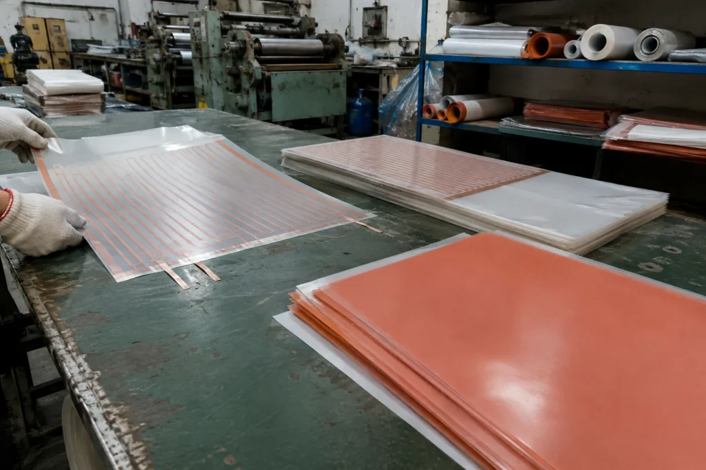
The customer outline comes in as a drawing or a DXF, and the element is laid out inside it: conductor gauge from the voltage, path length from the resistance, pitch from the watt density wanted at each part of the surface. Where the load needs more heat at the edges than in the middle, that is decided here, in the geometry, not later with more power. The insulation, the foil or wire and the adhesive for that build are then drawn from stock and staged together as one kit.
Calculated resistance and watt density checked against the construction limits before any tooling is cut; every material lot recorded against the works order.
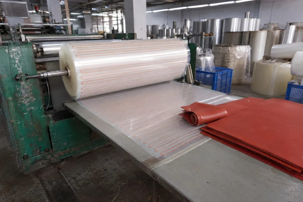
Film and silicone sheet are fed from the roll and cut to sheet, handled flat and kept clean. A fingerprint, a crease or a speck of dust trapped under the insulation becomes a void after pressing, and a void is a place the heat cannot leave from.
Sheet cleanliness and flatness checked at feed; material lot number stays with the sheet through to the finished part.
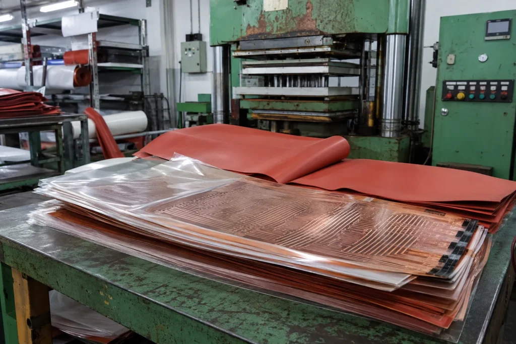
Wire-wound elements are wound on a glass carrier at the calculated pitch; etched-foil circuits are photo-imaged and etched from Inconel or copper foil to a trace width held within 0.05 mm. That tolerance is what makes the resistance repeatable from lot to lot, which is what makes the temperature repeatable. The element and its sensor are then stacked between the insulation sheets in the order the drawing specifies.
Trace width and element resistance measured before lamination — a circuit out of tolerance is scrapped here, not after it is sealed inside the part.
The lay-up is pressed under heat: silicone is vulcanised, polyimide and PET are laminated with a high temperature adhesive, epoxy plates are potted under vacuum so no voids are left anywhere in the heat path. A void is not a cosmetic defect — it is a place the heat cannot leave from, and it becomes the hot spot that ends the part.
Press temperature, pressure and dwell recorded per lot; potted plates checked for voids.
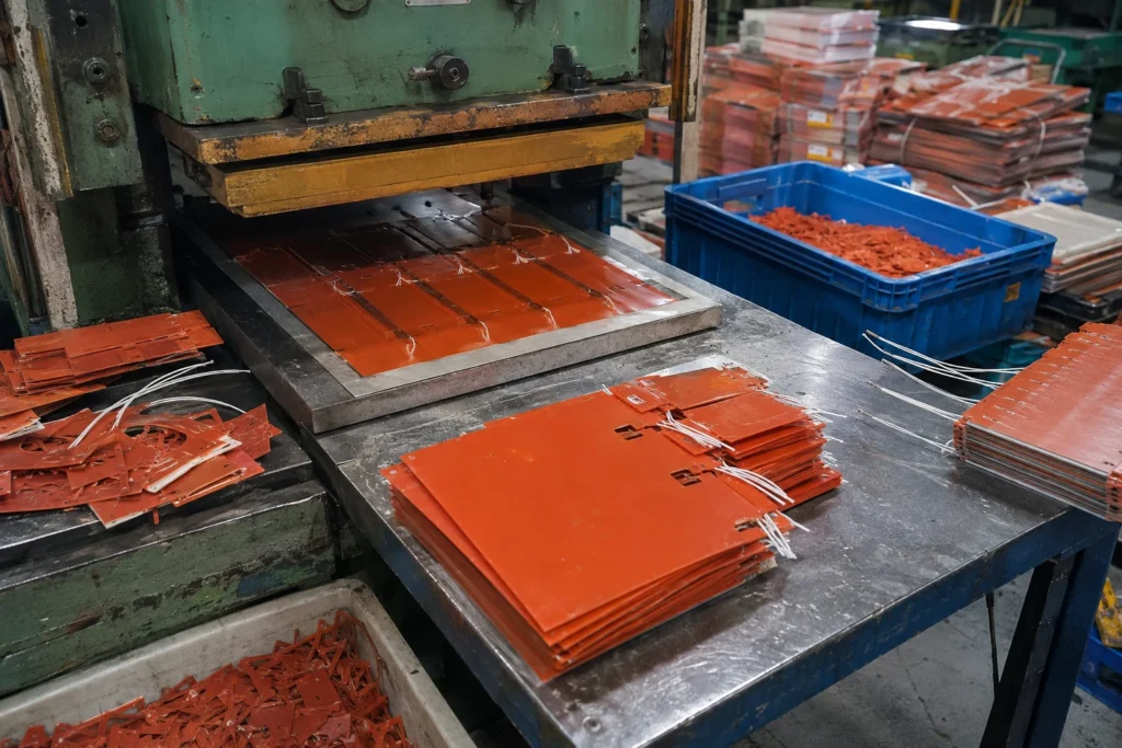
The outline is die cut with radiused corners — a die does not cut a sharp inside corner, and a sharp corner in a film is where a tear starts. Cut-outs, sensor windows and mounting holes come out in the same operation, which is why they have to be on the drawing before the tool is made rather than added afterwards.
Outline to ±0.5 mm on film, ±1.5 mm on silicone, gauged against the first-off sample for the tool.
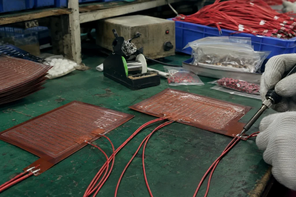
Leads are crimped or soldered at the exit and strain relieved, then connectors are fitted to the harness drawing so the assembly line never has to solder. The lead is worth as much attention as the heater: its jacket rating is frequently the lowest temperature limit in the whole assembly, and the exit is where a flexible heater is handled and where it fails if the relief is wrong.
Lead pull-out tested per lot; jacket rating and connector part number checked against the drawing rather than against the last order.
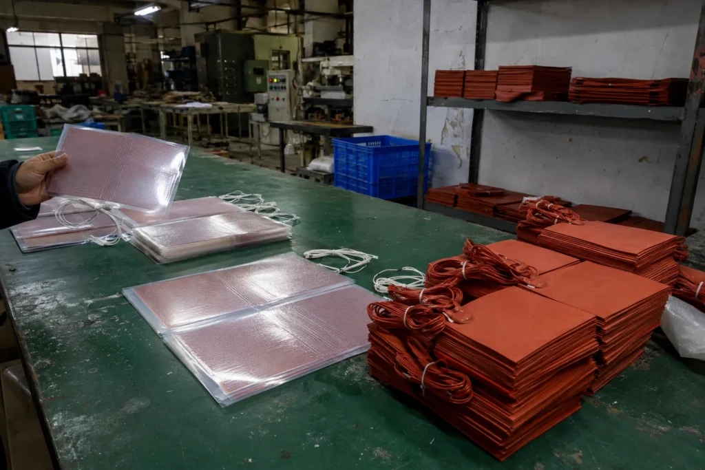
Every heater is measured for resistance against the drawing, then held at its dielectric test voltage for one minute element-to-surface, then measured again for insulation resistance. All three on every piece rather than on a sample, because a heater that fails insulation in service fails it into whatever it is bonded to. Units are sorted and any that miss the ordered tolerance are pulled here.
Resistance to the ordered tolerance; dielectric withstand and insulation resistance above 100 MΩ, logged per unit.
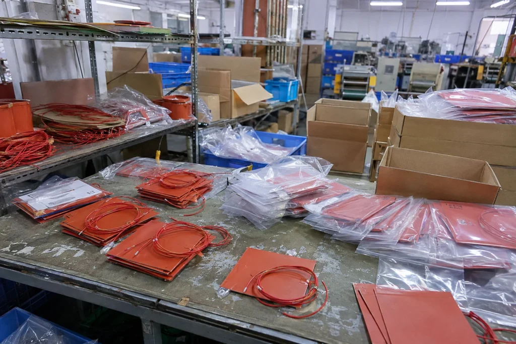
Sample units from every lot are run under power on a representative heat sink and imaged, because a hot spot is invisible to a resistance meter and obvious to a thermal camera. The lot then ships with its test record, and the lot number travels in the carton so a field failure can be traced back to the reel of foil it came from.
Thermal uniformity imaged per lot; full traceability from carton back to raw material.
Constructions are built and tested to UL 499, IEC/EN 60335 and UL 94 V-0, under RoHS and REACH, and where the programme requires it under IATF 16949 or ISO 13485. A made-to-drawing outline does not carry its own certificate — the construction is what is certified, and the end product carries the approval.
Insulation system, watt density, resistance tolerance, dielectric test voltage, sensor type and placement, lead gauge and termination, adhesive, marking, test records, packaging and documentation are all confirmed on the drawing before production starts.
Send the outline, the supply voltage, the power or the temperature you need to hold, what the heater is bonded to, the ambient it works in and the quantity. That is everything a quotation needs; anything missing is what an email round trip is usually spent on.