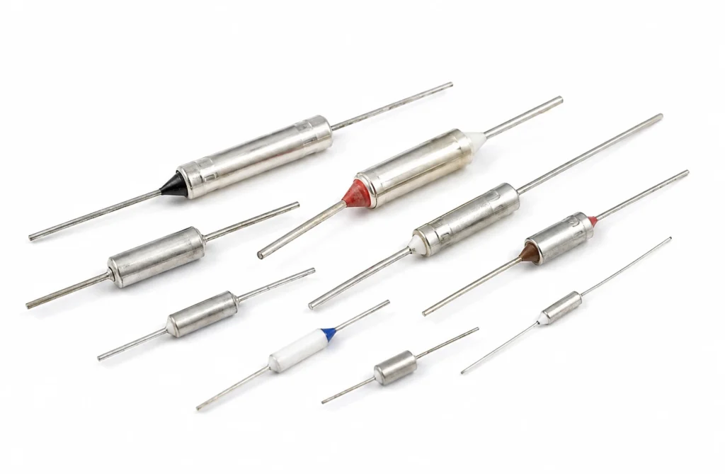
Working temperature page for thermal cutoffs and one-shot fuses at 150 °c to 200 °c. What survives this band, what stops just below it, why the boundary is where it is, and how the temperature is actually measured and held.
What the 150 °C to 200 °C Band Requires
The top of the flexible polymer range. Silicone rubber and polyimide both run continuously at 200 °C; above it both degrade, and no amount of derating changes that.
| Band | 150 °C to 200 °C |
|---|---|
| This construction, continuous | 240 °C |
The band sits comfortably inside the 240 °C ceiling, which is where a heater should be specified: the margin between the working temperature and the insulation limit is what absorbs a poor thermal path, a warm ambient and a control overshoot without shortening the life of the part.
Why the Boundary Is Where It Is
200 °C is the top of the flexible polymer range. Silicone rubber and polyimide both run there continuously, and both degrade above it — silicone hardens and loses its tear strength, polyimide embrittles. No derating changes either.
Cross this line and the construction changes completely: fired thick film on stainless or alumina, or a mica-insulated element. Those parts are rigid, clamped and made to a different drawing, so the boundary is a redesign rather than a substitution.
What a Thermal Cutoffs and One-Shot Fuses Is
The last line of protection: a fuse that opens once at a fixed temperature and never closes again, fitted where a resettable thermostat would let a fault repeat.
A bimetal disc that opens a contact at a fixed temperature. It is not an accurate controller and is not meant to be one: it is the device that decides whether the heater around it survives a fault, and it is specified by its open temperature, its reset behaviour and the current it can break.
The heat leaves through whatever the component is clamped or bonded to; a sensing component adds no heat of its own and simply has to be in thermal contact with the thing it is reporting on.
| Total thickness | Component |
|---|---|
| Maximum size, one piece | Component |
| Continuous working temperature | 240 °C |
The continuous limit of 240 °C is set by the insulation system. The element alloy would run far hotter; it is never the element that decides.
Which Temperature Is Being Held
Three temperatures matter and they are not the same number: the element temperature, the temperature of the surface being heated, and the ambient. A heater rated for a continuous working temperature is rated at the element — the hottest point in the assembly, and the one nothing on the outside is measuring.
The gap between element and surface is the thermal path. Bonded to metal it may be a few degrees; across an air gap, a void in the adhesive or a dry clamped joint it can be tens of degrees, and every one of them appears at the element rather than at the load.
Control and Protection
This heater has no way of limiting its own temperature. Resistance heating draws roughly the same power whatever the temperature, so with the load removed, the fluid gone, the fan stopped or the sensor open circuit, the element keeps producing watts until something stops it.
The design must therefore contain a control device and, separately, a protective one: a controller with a sensor to hold the set point, and a bimetal thermostat or a one-shot thermal cutoff wired in series with the element to open the circuit if the loop ever fails. The two are not interchangeable — a controller that has lost its sensor cannot protect anything, which is exactly the fault the cutoff exists for.
How This Construction Fails
- Loss of the control loop. An open-circuit sensor, a welded relay contact or a controller in manual leaves the element at full power with nothing watching it — the case the series thermal cutoff exists for, and the reason it must not be omitted to save a part.
- Measuring the wrong thing. A sensor in the air near a heated plate reports the air, and the loop holds the air where the specification wanted the plate. Nothing in the instrument can detect this.
Where This Construction Is the Wrong Answer
- Do not plan on running above 240 °C. That ceiling belongs to the insulation system, not to the element alloy, and it is not a figure that derating extends — past it the insulation degrades and the dielectric strength goes with it.
- Do not rate this component as though it were the heater. It carries a contact rating or a tolerance class; the heater next to it decides the power, the watt density and the temperature the assembly reaches.
How to Specify One
This is a made-to-drawing part, so there is no catalogue number to quote. A quotation is built from the following, and the more of it that arrives with the enquiry the fewer rounds it takes:
- The temperature to be sensed or switched, and the tolerance the application actually needs.
- Where the component sits — against the element, in the potting, on the load, or in the airflow.
- The electrical duty: for a switching device, the voltage, the current and whether the load is AC or DC.
- Lead length, insulation and termination, and whether the component is fitted by us into a heater assembly or supplied loose.
- The standard the end product is certified to, so the component chosen is one that fits inside that approval.
Lead time: Samples 7-10 days from approved drawing; production 15-20 days.
Thermal Cutoffs and One-Shot Fuses — Capability Table
These are process limits for the construction, not the specification of one stocked item. Every line is what the factory can hold; what your part holds is fixed on your drawing.
| Parameter | Specification | Limit / note |
|---|---|---|
| Type | One-shot thermal cutoff (TCO), non-resetting | Once it opens, the heater is dead and the fault has to be found |
| Function temperature | +72 u00b0C to +240 u00b0C, fixed | Chosen above the working temperature and below the damage temperature |
| Tolerance | 0 / -5 u00b0C on the function temperature | |
| Rating | 10 A at 250 V AC | |
| Holding temperature | Typically 15 u00b0C to 25 u00b0C below the function temperature | Continuous operation above it will eventually trip the fuse anyway |
| Mounting | In series with the element, inside the insulation | Outside the insulation it protects nothing |
| Why one-shot | A resettable thermostat can cycle on a fault indefinitely | Some faults must stop the product permanently, and this is the component that does it |
| Certifications | UL, VDE, CQC on the component |
Figures are the published tolerance and rating bands of the standard sensor and control components fitted to these heaters. Sensor tolerance classes follow IEC 60751 for RTDs and IEC 60584 for thermocouples; thermostat and thermal cutoff ratings are the component manufacturers' own.