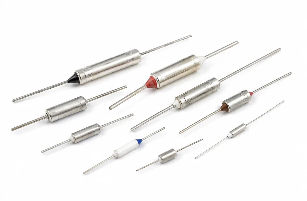
The last line of protection: a fuse that opens once at a fixed temperature and never closes again, fitted where a resettable thermostat would let a fault repeat. Thermal Cutoffs and One-Shot Fuses are specified where a design calls for measuring, limiting or switching the temperature of a heated assembly — the half of a heating system that decides what happens when something goes wrong. None of these parts produces heat. What they do is decide when the heater is on and what happens when the control fails, which is the difference between an assembly that holds a set point and one that burns. They are specified together with the heater, not after it. Below: typical end uses by industry, the specification checklist, the control and protection the construction requires, installation practice, and the applications it is not suited to.
Typical Applications for Thermal Cutoffs and One-Shot Fuses
The assemblies and sectors where this construction is specified:
- OEM equipment manufacture: designed-in heating on new equipment, specified from the surface, the target temperature and the available power at the design stage rather than retrofitted afterwards.
- Retrofit and equipment upgrades: replacing a failed or unsuitable heater on existing equipment, where the outline, the voltage and the mounting all have to match what is already there.
- The last line of protection: fitted behind a resettable device, where a fault must be stopped once and investigated rather than allowed to cycle.
- Independent over-temperature protection: the device in the heater circuit that acts when the controller, the sensor or the firmware is the thing that failed.
- Battery packs and energy storage: pack and cell-surface measurement feeding a BMS, plus an independent cutoff that does not depend on the same firmware that decided to switch the heater on.
How to Specify Thermal Cutoffs and One-Shot Fuses for Your Application
- Footprint and rating: This is a component with a standard footprint rather than a made-to-drawing outline: it is ordered by its rating and its physical form, and the design work is in how it is mounted and what it is thermally connected to.
- Opening temperature, differential and contact rating: These three fields are the whole specification of a bimetal device. The differential in particular is fixed by construction: on an assembly with little thermal mass it is the whole temperature swing the load will see.
- Where it is fitted, and to what: A temperature part measures its own temperature and nothing else. Specify the mounting — bonded to the heated surface, clamped under a lug, potted into the assembly, laminated inside the heater — because the thermal path between the part and the thing you actually care about is the dominant source of error, and it is far larger than any tolerance in the datasheet.
- Range and accuracy against the duty: State the working range, the accuracy you need across it and whether the loop will be calibrated or validated. Accuracy over a narrow band near ambient and accuracy across 400 °C are different specifications and lead to different parts.
- Protection is separate from control: A control sensor and a protective device are two functions and should be two parts. If the same element both regulates and protects, then any fault that disables it removes both, which is the failure the protective device existed for.
- Electrical rating of the contacts: For a switching device, state the load current, the voltage and whether it is inductive. A thermostat rated for a resistive load and used to switch a contactor coil will weld its contacts long before it wears out thermally.
- Supply voltage: State the supply voltage: this construction is wound or printed for 12 V DC, 24 V DC, 110-120 V AC or 220-240 V AC, and it is built for the one voltage ordered rather than being switchable between them. At low voltage the current is the problem — a 120 W heater at 12 V draws 10 A, and the lead gauge, the connector and the switching device all have to carry it. At mains voltage the insulation, the earthing or double insulation and the creepage distances become part of the construction, and a low wattage at 230 V means a very fine, very long element that is harder to build reliably than its low-voltage equivalent.
- Temperature limit: The continuous limit is 240 °C, and it belongs to the insulation system rather than to the element. Nichrome, Inconel and fired resistor pastes all survive far beyond it; what fails first is the material holding them, and no derating of the wattage moves that number. State the maximum temperature the assembly can reach under fault as well as the working set point, because it is the fault case that has to stay inside this number.
- Control and protection: This construction does not limit itself in any way. At rated voltage into a surface that has lost contact, run dry or lost its coolant, it goes on taking full power until the insulation fails, so a thermostat or a thermal cutoff sized to the assembly — not to the heater — belongs in the design and in the schematic. Where a fault must not be allowed to repeat itself, a one-shot thermal cutoff goes behind the resettable device, because a bimetal thermostat cycling on a genuine fault will cycle for as long as the power is on.
- Mounting: State how and where the part is fitted and what it is thermally connected to. For a sensing or switching device the thermal path to the thing being measured is the dominant source of error, and it is decided entirely by the mounting.
- Certification of the construction: The constructions behind this product are built and tested to IEC 60730, IEC/EN 60335, RoHS & REACH, CE Marking, UL 94 V-0. That is a statement about a construction — its insulation system, its creepage and clearances, its earthing, its marking and its tests — and not a claim that a particular made-to-drawing outline carries an approval of its own. Say at the enquiry which standard your end product is certified to, because it constrains the build rather than being added to it afterwards.
- Leads and termination: State the wire type, gauge, length and exit direction, and the termination — bare, ferrule, ring, spade or a specific connector housing. The lead exit is a mechanical design decision: it is where a flexible heater is most often folded during assembly, and the joint behind it cannot be inspected once the part is built.
Control, Protection and What Happens at a Fault
This construction does not limit itself in any way. At rated voltage into a surface that has lost contact, run dry or lost its coolant, it goes on taking full power until the insulation fails, so a thermostat or a thermal cutoff sized to the assembly — not to the heater — belongs in the design and in the schematic. Where a fault must not be allowed to repeat itself, a one-shot thermal cutoff goes behind the resettable device, because a bimetal thermostat cycling on a genuine fault will cycle for as long as the power is on.
- The control device: A sensor on the load and a controller — on/off where the load has thermal mass and a few degrees of swing is acceptable, PID where the set point has to be reached without overshoot. This is what holds the temperature; it is not what protects the assembly.
- The limit device: A bimetal thermostat or a thermal cutoff, sensing the heater or the hottest point of the assembly, wired so that it interrupts the heater regardless of what the controller is doing. It has to be independent of the control sensor: a broken sensor wire that the controller reads as cold is one of the commonest ways a heating assembly ends up at full power.
- The fault case to design against: Ask what happens if the heater loses contact with its load, if the fluid stops, if the fan stops, or if the controller output sticks on. In every one of those the heater goes on delivering full power into a surface that is no longer carrying it away, and the answer has to be a device that acts, not a calculation showing it would take a long time.
Fitting, Placement & Wiring Practice
- Fit the part in the thermal path you intend to measure, not near it. A sensor in the air a few millimetres from a heated plate reads a temperature that plate passed through several seconds earlier, and the loop built on it will overshoot every time it is switched on.
- Use a thermal interface — paste, pad or adhesive — under any surface-mounted device, and clamp it against the metal rather than the insulation.
- Keep sensor wiring away from the heater leads and from switching devices. A low-level signal running parallel to a switched mains conductor picks up exactly the noise that makes a stable loop look unstable.
- For a resistance sensor, account for the lead resistance: two-wire wiring puts the whole cable resistance into the reading, and three-wire or four-wire connection exists to remove it.
- Fit a protective device so it senses the hottest point of the assembly under fault, not the most convenient point during assembly.
Common Specification Mistakes with Thermal Cutoffs and One-Shot Fuses
- Treating an operated cutoff as a consumable and replacing it without finding out why it operated. It is designed to open once precisely so that the fault gets attention.
- Placing the sensor where it is easy to fit rather than where the temperature matters, then tuning the controller to compensate for a lag that is in the mechanics.
- Using one part for both control and protection. When it fails, the assembly loses its regulation and its safety net in the same instant.
- Ignoring hysteresis on a mechanical thermostat. The open and close temperatures are different by design, and on an assembly with little thermal mass that difference is the whole swing the load will see.
- Tuning a PID loop on the bench in still air and shipping it into a duct, a cabinet or a fluid. The disturbance model is completely different and the tuning does not transfer.
Where Thermal Cutoffs and One-Shot Fuses Are Not the Right Choice
- Not a substitute for the protective device required by the appliance or machinery standard the end product is certified to — that requirement is about the fault case, not about the accuracy of the control.
- Not a heat source of any kind: these parts sense and switch, and every duty on this page also needs the heater chosen for it.
- Not usable outside the range of the sensing element. Beyond it the reading does not simply become inaccurate, it becomes meaningless, and the loop acts on it anyway.
- Not a fix for a bad thermal design. If the heater and the load are poorly coupled, a better sensor measures the problem more precisely without changing it.
- Not as its own protection. This construction has no self-limiting behaviour, so it is never the right answer for a design that has nowhere to put a thermostat or a thermal cutoff.