
Thermal Cutoffs and One-Shot Fuses are temperature sensing & control, produced to a dimensioned drawing or a DXF. The table below is a statement of what this factory can build rather than a list of what is on a shelf; the sections after it cover the two things that decide whether a heater survives its duty — how much power per square centimetre it carries, and what stops it.
What Are Thermal Cutoffs and One-Shot Fuses?
Thermal Cutoffs and One-Shot Fuses are temperature sensing & control. They are specified by rating together with the outline drawing, the wattage or the temperature to be held, and what the heater is bonded to — that last one decides the permissible watt density and is the question a quotation cannot skip. The construction is built and tested to IEC 60730 / IEC 60335 / RoHS.
Construction & Insulation System
These are the components that make a heated product safe and accurate, and they are not interchangeable with each other. A bimetal thermostat or a one-shot thermal cutoff protects; a thermistor, RTD or thermocouple measures; a controller closes the loop. Using one component for two of those jobs leaves the product with no protection in exactly the case protection exists for — the loop failing on.
Typical Applications
The protection and the measurement that every heated product needs: a thermostat or thermal cutoff in series with the element, a thermistor, RTD or thermocouple reading the surface that matters, and a controller closing the loop around them. Read the full application guide for Thermal Cutoffs and One-Shot Fuses →
Specifying the Thermal Cutoffs and One-Shot Fuses
The supply is usually already fixed by the equipment the device goes into: 12 V DC, 24 V DC and 110-120 V AC. Each page covers the switching or sensing arrangement at that supply, the contact and lead rating it needs, and how the over-temperature path is kept separate from the control path.
The material the device is housed and insulated in decides where it can be mounted and how hot the mounting face may get: Aramid Paper (Nomex type). Each page states the ceiling that material sets and the dielectric withstand it gives.
Specified by the temperature it has to read or switch at: 80 °C to 120 °C and 120 °C to 150 °C. Each pages covers the tolerance and the class that band is available in, and where the sensor has to sit to read the surface that actually matters.
This device is built and tested to IEC/EN 60335 and RoHS & REACH — worth checking against the standard your own end product is certified under, because a part built to one scope does not automatically satisfy another. For the equipment and duties this device is actually specified for, see where thermal cutoffs and one-shot fuses are used.
Manufactured in our own plant
This heater is laid out, wound or etched, laminated, cut, tested and imaged in-house. The stages below are where its resistance tolerance, its temperature uniformity and its insulation integrity are actually decided.
-
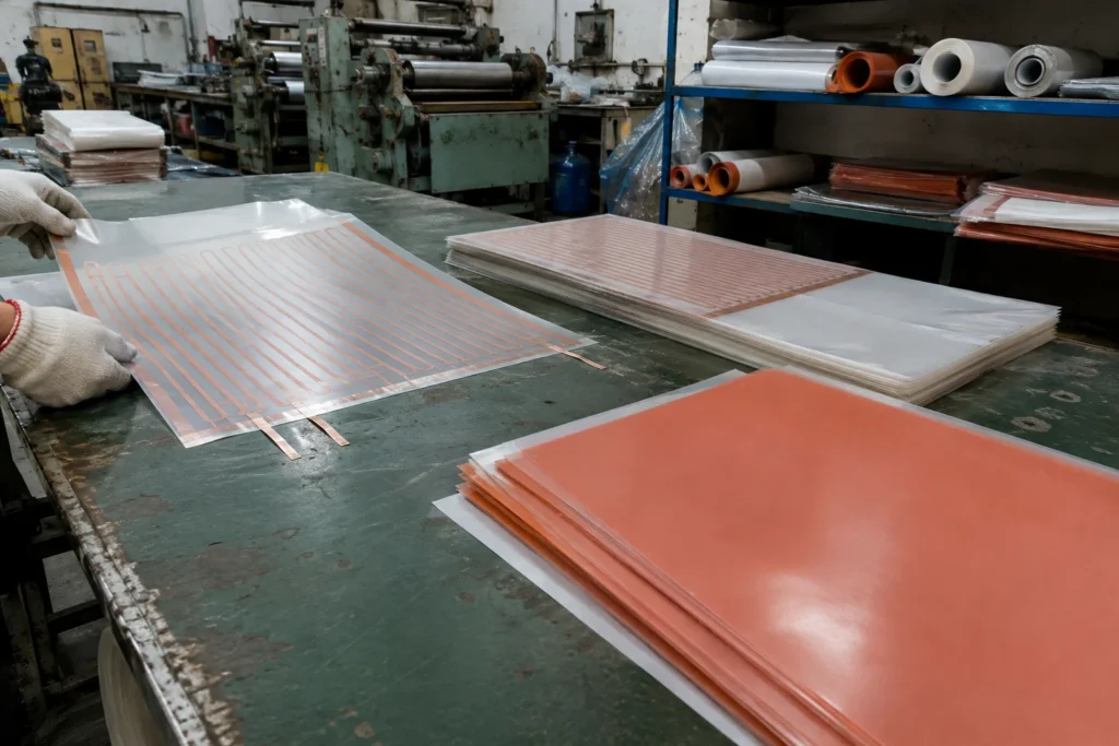
01 Circuit design & material preparation
The customer outline comes in as a drawing or a DXF, and the element is laid out inside it: conductor gauge from the voltage, path length from the resistance, pitch from the watt density wanted at each part of the surface. Where the load needs more heat at the edges than in the middle, that is decided here, in the geometry, not later with more power. The insulation, the foil or wire and the adhesive for that build are then drawn from stock and staged together as one kit.
Calculated resistance and watt density checked against the construction limits before any tooling is cut; every material lot recorded against the works order.
-
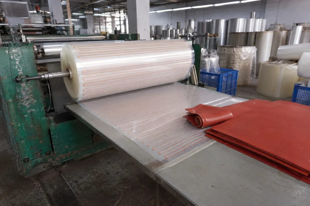
02 Roll feeding & sheet handling
Film and silicone sheet are fed from the roll and cut to sheet, handled flat and kept clean. A fingerprint, a crease or a speck of dust trapped under the insulation becomes a void after pressing, and a void is a place the heat cannot leave from.
Sheet cleanliness and flatness checked at feed; material lot number stays with the sheet through to the finished part.
-
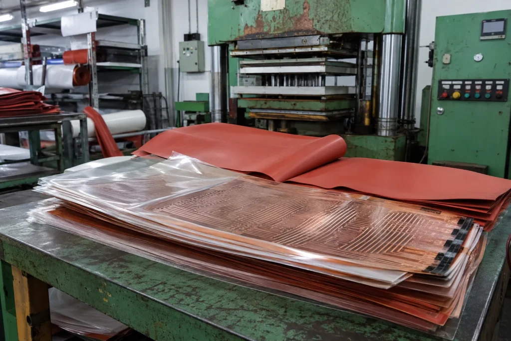
03 Element preparation & lay-up
Wire-wound elements are wound on a glass carrier at the calculated pitch; etched-foil circuits are photo-imaged and etched from Inconel or copper foil to a trace width held within 0.05 mm. That tolerance is what makes the resistance repeatable from lot to lot, which is what makes the temperature repeatable. The element and its sensor are then stacked between the insulation sheets in the order the drawing specifies.
Trace width and element resistance measured before lamination — a circuit out of tolerance is scrapped here, not after it is sealed inside the part.
-
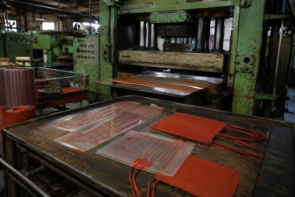
04 Lamination & vulcanising
The lay-up is pressed under heat: silicone is vulcanised, polyimide and PET are laminated with a high temperature adhesive, epoxy plates are potted under vacuum so no voids are left anywhere in the heat path. A void is not a cosmetic defect — it is a place the heat cannot leave from, and it becomes the hot spot that ends the part.
Press temperature, pressure and dwell recorded per lot; potted plates checked for voids.
-
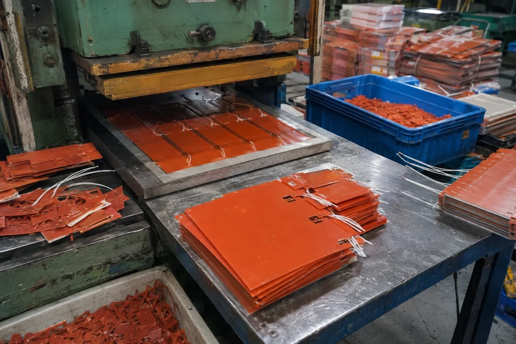
05 Die cutting
The outline is die cut with radiused corners — a die does not cut a sharp inside corner, and a sharp corner in a film is where a tear starts. Cut-outs, sensor windows and mounting holes come out in the same operation, which is why they have to be on the drawing before the tool is made rather than added afterwards.
Outline to ±0.5 mm on film, ±1.5 mm on silicone, gauged against the first-off sample for the tool.
-
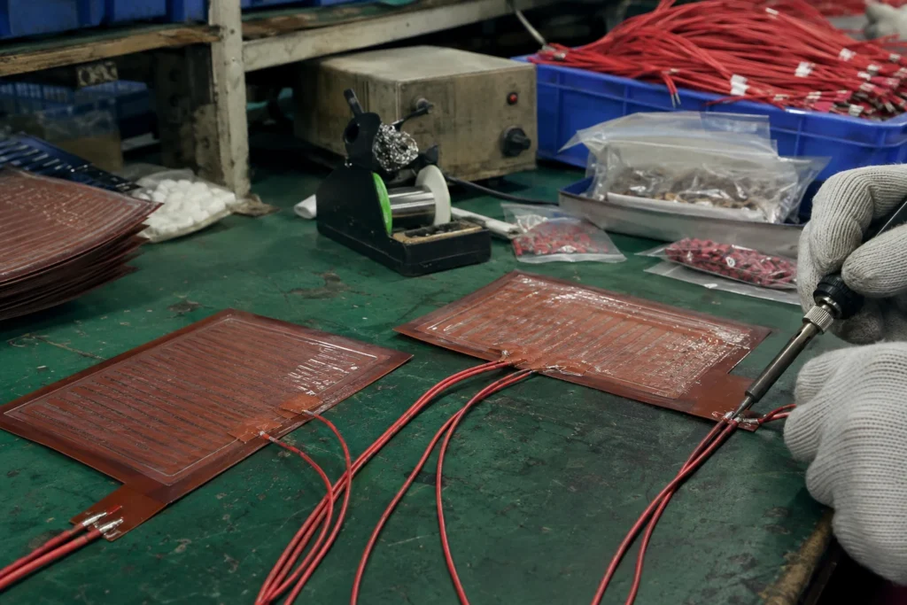
06 Leads, terminals & connectors
Leads are crimped or soldered at the exit and strain relieved, then connectors are fitted to the harness drawing so the assembly line never has to solder. The lead is worth as much attention as the heater: its jacket rating is frequently the lowest temperature limit in the whole assembly, and the exit is where a flexible heater is handled and where it fails if the relief is wrong.
Lead pull-out tested per lot; jacket rating and connector part number checked against the drawing rather than against the last order.