Stainless Steel Thick Film Heaters wound for 380-415 V AC. The supply decides the element: 3000 W at this voltage is 48.1 Ω, and the same 3000 W at a tenth of the voltage would be a hundredth of the resistance in a conductor ten times heavier. This page covers the circuit, the isolation, the switching and what the construction can be built to at this supply.
The Element at 380-415 V AC
Two equations do all the work: P = V²/R and I = P/V. At 380-415 V AC, 3000 W is 48.1 Ω and 7.89 A single phase, or 4.56 A per phase balanced across three (P = √3 · V · I).
| Worked example | 3000 W at 380-415 V AC |
|---|---|
| Element resistance, R = V²/P | 48.1 Ω |
| Current, I = P/V | 7.89 A |
The span matters more than the example. At 380-415 V AC a 20 W element is 722 Ω and a 500 W element is 288.8 Ω — a factor of twenty-five in resistance, met by changing the conductor cross-section and the length of the path, both of which are constrained by the outline.
At mains voltage the difficulty is the opposite one. Current is modest — 7.89 A for the worked example — but the element is a long, fine conductor, and a low-wattage heater at 380-415 V AC is the hardest thing in this catalogue to build: 20 W means 722 Ω, which is a very long track to fit inside a small outline without the pitch becoming so tight that adjacent runs interact.
Where the arithmetic will not fit the outline, the usual answers are a lower supply voltage with a small power supply behind it, several circuits in series, or a different construction entirely. What does not work is thinning the conductor further: the track becomes the fuse.
Resistance tolerance is u00b110% standard, u00b15% selected, and power follows resistance inversely: a u00b110% standard, u00b15% selected tolerance band is the same band on the delivered wattage. Where the wattage matters — a warm-up to a deadline, a pack of heaters that must match — say so on the enquiry and the tighter band is selected and tested.
Isolation, Earthing and Safety Class
380-415 V AC is a mains supply, and the construction is built to match: mains-rated insulation, a protective earth connection or a double-insulated build, and creepage and clearance distances held between the element and any accessible surface.
Leakage current is the figure that surprises people. A large heated area behaves as a distributed capacitance to earth, so a big mains heater has a measurable leakage even when it is perfectly sound, and an RCD protecting several of them can trip on the sum. Where several elements share a circuit, allow for the total.
| Dielectric withstand | 2500 V AC, 1 minute |
|---|---|
| Insulation resistance | greater than 100 Mu03a9 at 500 V DC |
Every heater is tested to these before it ships, element to any exposed surface. A dielectric test is a pass or a fail, not a measurement — a part that passes at 2500 V is not one that may be run at 2500 V.
What a Stainless Steel Thick Film Heaters Is
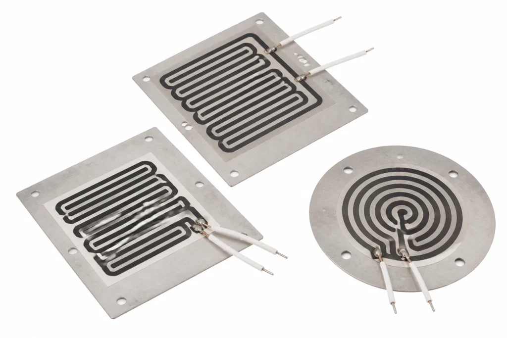
Resistor tracks fired onto 304 or 316 stainless: the heated surface is the pressure boundary itself, so there is no gasket, no interface and nothing to conduct across.
Dielectric and resistor pastes screen printed onto stainless steel or alumina and fired at around 850 °C, then laser trimmed to resistance. There is no separate element and no interface: the heated surface is the substrate itself. Rigid: the fired layers will not tolerate flexing, and a dented substrate is a scrapped heater.
The heat leaves through a clamped joint, and a clamped joint is only as good as the pressure and the flatness behind it. A thermal interface material or a thin film of thermal grease fills the gaps that machining leaves; without one, contact happens at the high spots and the element runs hotter than the plate it is bolted to.
| Element | fired resistor paste, laser trimmed |
|---|---|
| Insulation system | fired glass dielectric on the substrate |
| Total thickness | 1.5 mm to 4 mm total |
| Maximum size, one piece | 200 x 400 mm |
| Continuous working temperature | 400 °C |
The continuous limit of 400 °C is set by fired glass dielectric on the substrate. The element alloy would run far hotter; it is never the element that decides.
Switching an AC Element
AC switching has a zero crossing to hide behind. A zero-cross solid state relay makes and breaks at the crossing, which all but removes the switching transient and the conducted emissions that go with it — worth having on any installation that also has to pass an EMC test.
Control by burst firing — whole cycles on, whole cycles off, over a period of a second or more — rather than by phase angle. Burst firing generates almost no harmonics; phase angle control chops the waveform and is the reason a heater ends up in the EMC report at all. A heater has enough thermal inertia that a one-second period is invisible at the surface.
Size the relay for the inrush, not the running current, and heatsink it: a triac or SSR drops around one volt per amp of load, and that is real power to be got rid of inside the panel.
Watt Density: the Two Figures
Watt density, not wattage, is what the construction is limited by. 5 W/cm² unbonded and 50 W/cm² bonded to metal are the limits for this build — so if the wattage is fixed by the duty, the area is what has to move.
Where the required power will not fit into the available area at the free-air figure, the answer is a better thermal path rather than a thinner margin: bond the whole face down, or add a spreader plate. On 150 cm² the difference is roughly 75 W against 75 W, which is usually the whole argument.
Thick film reaches these densities because the heated surface is the substrate — there is no interface between element and load to conduct across. That is also why dry-run protection is not optional: with the fluid gone, so is the entire thermal path, and the fired layers reach their limit in seconds rather than minutes.
Attachment and Thermal Contact
The part is clamped, not bonded. What matters at the joint is flatness, contact pressure and a thermal interface material to fill what machining leaves behind — a dry joint between two nominally flat surfaces touches on perhaps a few percent of its area.
Clamp evenly and to a torque, not to feel. A ceramic substrate in particular survives 400 °C far better than it survives one bolt pulled down harder than the other three.
From the capability table: Bolted, brazed or welded into the assembly; flatness of the mating face is critical.
The joint between the heated surface and the load carries every watt the element makes. Fill it: an interface pad, a thin film of thermal grease or a bonded assembly. Two dry surfaces bolted together are a thermal resistance, and that resistance appears as element temperature.
Control and Protection
This heater has no way of limiting its own temperature. Resistance heating draws roughly the same power whatever the temperature, so with the load removed, the fluid gone, the fan stopped or the sensor open circuit, the element keeps producing watts until something stops it.
The design must therefore contain a control device and, separately, a protective one: a controller with a sensor to hold the set point, and a bimetal thermostat or a one-shot thermal cutoff wired in series with the element to open the circuit if the loop ever fails. The two are not interchangeable — a controller that has lost its sensor cannot protect anything, which is exactly the fault the cutoff exists for.
On a fluid heater the limit device belongs on the substrate, close to the resistor, not downstream in the water. Downstream is where the temperature has already gone wrong; the substrate is where it goes wrong first, and at these watt densities the interval between the two is short.
Sensors can be built into the part: NTC thermistor, PT100 or PT1000 RTD, or a K-type thermocouple, fitted under the same insulation and tested with the heater as one assembly. A sensor laminated into the heater reads the heater; a sensor on the load reads the load. Both are legitimate, and the drawing has to say which is wanted.
How This Construction Fails
- Run at the bonded watt density in free air. The insulation reaches its limit within minutes and the element burns through where the local density is highest. Specify at 50 W/cm² only where the heater is genuinely bonded to metal over its whole area; unbonded, the figure is 5 W/cm².
- Loss of the control loop. An open-circuit sensor, a welded relay contact or a controller in manual leaves the element at full power with nothing watching it — the case the series thermal cutoff exists for, and the reason it must not be omitted to save a part.
- Dry running. With the fluid gone the entire thermal path is gone, and at these densities the fired layers and the trim are destroyed in seconds. Flow or level interlocks, not a downstream thermostat, are what prevent it.
- Scale on the wetted face. A layer of scale is a thermal resistance in exactly the wrong place: the substrate temperature rises to push the same power through it, and the failure looks like an overpowered heater rather than a fouled one.
How to Specify One
This is a made-to-drawing part, so there is no catalogue number to quote. A quotation is built from the following, and the more of it that arrives with the enquiry the fewer rounds it takes:
- An outline drawing, or a sketch with dimensions: overall size, holes, cut-outs, radii and the lead exit position.
- The supply voltage, and whether it is AC or DC. The element is wound for one voltage; it is not a switchable range.
- The power required, or — better — the temperature to be reached and the mass or flow it has to be reached in. Given the second, the wattage can be calculated instead of guessed.
- What the heater is attached to, and how. This is what decides which watt density figure applies, and it is the question a quotation cannot proceed without.
- The ambient, and the lowest temperature the assembly must start from. A heater sized for a 20 °C start is undersized for a -30 °C one.
- Duty cycle: continuous, intermittent, or a warm-up to a deadline. Time to temperature is a specification, not a by-product.
- Sensor and protection: which sensor, where it goes, and which limit device is fitted in series with the element.
- The certification the end product is built to, named on the enquiry rather than after approval.
- Quantity and target price, because the construction that is right for fifty pieces is often not the one that is right for fifty thousand.
- The fluid, its flow rate and its inlet temperature, and how a dry-run condition is detected in your system.
Lead time: Samples 7-10 days from approved drawing; production 15-20 days.
Stainless Steel Thick Film Heaters — Capability Table
These are process limits for the construction, not the specification of one stocked item. Every line is what the factory can hold; what your part holds is fixed on your drawing.
| Parameter | Specification | Limit / note |
|---|---|---|
| Construction | Glass dielectric and resistor pastes screen printed and fired onto the substrate, then laser trimmed to resistance | Fired, bonded or encapsulated as a single assembly |
| Substrate | 304 or 316 stainless steel, 0.8 mm to 3 mm | The substrate carries the heat and the mechanical load |
| Thickness | 1.5 mm to 4 mm total | Substrate plus element system |
| Maximum size, one piece | 200 x 400 mm | Limited by the firing or curing fixture |
| Dimensional tolerance | u00b10.2 mm on the substrate, u00b10.1 mm on printed features | On the machined substrate |
| Supply voltage | 12 V DC to 400 V AC | Circuit is designed for the ordered voltage |
| Resistance tolerance | u00b110% standard, u00b15% selected | Thick film resistors are laser trimmed where a tighter band is required |
| Watt density | 5 W/cmu00b2 typical, 50 W/cmu00b2 maximum in a wetted application | Achievable because the heat is generated in the surface being cooled |
| Maximum working temperature | +400 u00b0C at the element system | Of the element system; the substrate itself tolerates more |
| Dielectric strength | 2500 V AC, 1 minute | One minute, circuit to substrate |
| Insulation resistance | greater than 100 Mu03a9 at 500 V DC | At 500 V DC |
| Terminations | Welded tabs, crimp terminals or soldered leads depending on temperature | Soldered, welded or crimped as the temperature allows |
| Mounting | Bolted, brazed or welded into the assembly; flatness of the mating face is critical | Flatness of the mating face matters more than clamping force |
| Sensor and control options | Printed PTC or NTC track, or a bonded thermocouple | Integrated into the same firing or bonded to the substrate |
| Certifications available | UL 499, IEC/EN 60335, RoHS, REACH, CE | Construction level |
| Why stainless | The wetted face is the substrate, so the water sees steel and the element sees no interface | This is the reason a thick film heater outperforms a tubular element in a flow heater |
| Thermal response | Under 1 second to full output | Almost no thermal mass between the resistor and the fluid |
Capability figures are this factory's process limits for fired thick film construction. Watt densities far above any flexible heater are achievable because the resistor is printed directly onto the surface being cooled — there is no interface and no adhesive in the heat path.