Working temperature page for c-profile pipe silicone heaters at 80 °c to 120 °c. What survives this band, what stops just below it, why the boundary is where it is, and how the temperature is actually measured and held.
What the 80 °C to 120 °C Band Requires
Battery operating windows, incubators, fluid warming and display heating. The upper limit of PET film, and the band where a low-cost printed heater stops being a candidate.
| Band | 80 °C to 120 °C |
|---|---|
| This construction, continuous | 200 °C |
| Limited by | fibreglass-reinforced silicone rubber |
The band sits comfortably inside the 200 °C ceiling, which is where a heater should be specified: the margin between the working temperature and the insulation limit is what absorbs a poor thermal path, a warm ambient and a control overshoot without shortening the life of the part.
Why the Boundary Is Where It Is
120 °C is where PET film stops. The polyester softens from about 130 °C and loses its dielectric strength as it softens, so the margin between working temperature and failure is thin — and a failure here is an electrical one, not a cosmetic one.
This is therefore the last band in which the cheapest thin heater is a candidate. Above it, the construction changes to silicone or polyimide, and the cost per square metre changes with it.
What a C-Profile Pipe Silicone Heaters Is
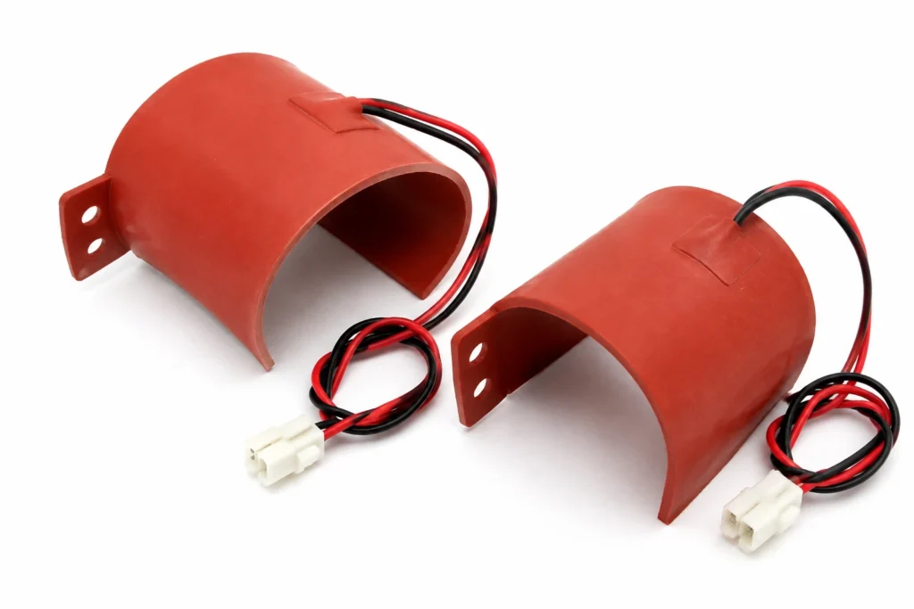
Pre-formed C-section silicone heaters that clip around a pipe, for freeze protection and for holding process fluid at temperature without a jacket.
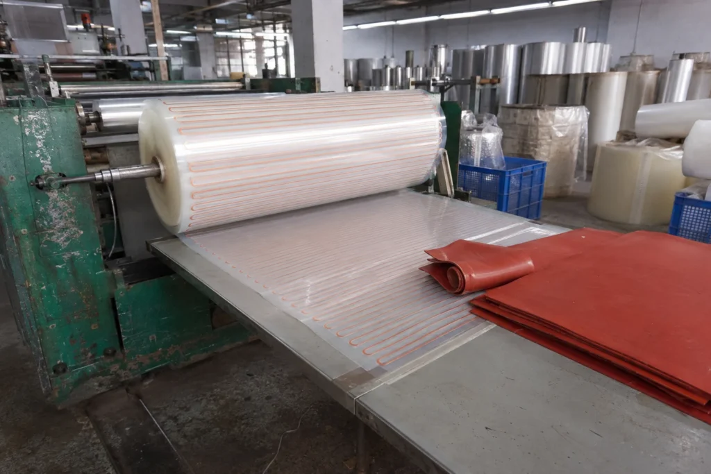
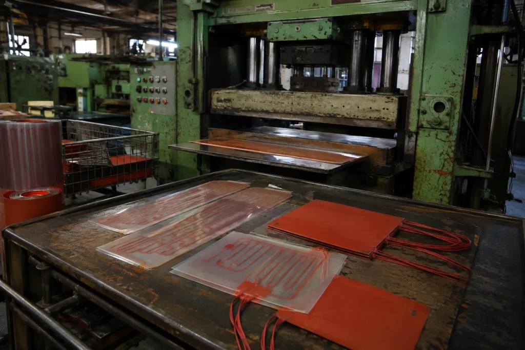
Nichrome resistance wire, or an etched Inconel foil circuit, vulcanised between two sheets of fibreglass-reinforced silicone rubber. The construction is about 1.2 to 2 mm thick, conforms to a curved surface, and holds its dielectric strength from -50 °C up to 200 °C continuously. Wrapped around a pipe, a drum or an IBC, the heated face is the inside of the wrap, so the useful watt density is the bonded figure only while the wrap is strapped down over its whole area — a blanket that has lifted away from the wall is running in free air at the point where it lifted.
The heat leaves through the bonded face. Everything that is not in contact with the load radiates and convects from the back of the heater instead, which at these thicknesses is a poor path — so an air gap under part of the outline is not a small loss of efficiency, it is a hot spot at that spot.
| Element | nichrome wire or etched Inconel foil |
|---|---|
| Insulation system | fibreglass-reinforced silicone rubber |
| Total thickness | 1.8 mm |
| Maximum size, one piece | 2000 mm long x 300 mm developed width |
| Continuous working temperature | 200 °C |
The continuous limit of 200 °C is set by fibreglass-reinforced silicone rubber. The element alloy would run far hotter; it is never the element that decides.
Which Temperature Is Being Held
Three temperatures matter and they are not the same number: the element temperature, the temperature of the surface being heated, and the ambient. A heater rated for a continuous working temperature is rated at the element — the hottest point in the assembly, and the one nothing on the outside is measuring.
The gap between element and surface is the thermal path. Bonded to metal it may be a few degrees; across an air gap, a void in the adhesive or a dry clamped joint it can be tens of degrees, and every one of them appears at the element rather than at the load.
Which is why sensor position is a drawing item. A sensor laminated into the heater protects the heater; a sensor on the load controls the load. Assemblies that have to do both carry two: a control sensor where the process is, and a limit device against the element.
Watt Density: the Two Figures
Two watt densities are quoted because there are two thermal situations. With nothing conducting heat away, 0.5 W/cm² is what the insulation survives. Bonded to a heat sink over the full outline, 3 W/cm² is. Anything in between depends on the quality of the joint, and the joint is the customer's to make.
The failure is silent and quick: the element does not know how it is mounted, so at 3 W/cm² in free air the heat simply accumulates in the insulation until it degrades. This is the single most common way these heaters are destroyed, and it happens on the first run rather than after a year.
Control and Protection
This heater has no way of limiting its own temperature. Resistance heating draws roughly the same power whatever the temperature, so with the load removed, the fluid gone, the fan stopped or the sensor open circuit, the element keeps producing watts until something stops it.
The design must therefore contain a control device and, separately, a protective one: a controller with a sensor to hold the set point, and a bimetal thermostat or a one-shot thermal cutoff wired in series with the element to open the circuit if the loop ever fails. The two are not interchangeable — a controller that has lost its sensor cannot protect anything, which is exactly the fault the cutoff exists for.
Sensors can be built into the part: NTC thermistor, PT100 or PT1000 RTD, or a K-type thermocouple, fitted under the same insulation and tested with the heater as one assembly. A sensor laminated into the heater reads the heater; a sensor on the load reads the load. Both are legitimate, and the drawing has to say which is wanted.
How This Construction Fails
- Run at the bonded watt density in free air. The insulation reaches its limit within minutes and the element burns through where the local density is highest. Specify at 3 W/cm² only where the heater is genuinely bonded to metal over its whole area; unbonded, the figure is 0.5 W/cm².
- Voids under the bond. Air trapped during application, a contaminated surface or an adhesive that never reached full cure all produce the same result: a patch with no thermal path, running far above the rest of the heater, which is where the failure starts.
- Loss of the control loop. An open-circuit sensor, a welded relay contact or a controller in manual leaves the element at full power with nothing watching it — the case the series thermal cutoff exists for, and the reason it must not be omitted to save a part.
- Mechanical damage at the edge. Silicone is tough but it tears from a cut, and a heater trimmed to fit on assembly has had its edge seal opened; moisture then tracks along the glass carrier to the element.
Other Constructions That Hold 80 °C to 120 °C
Constructions in this catalogue that will hold 80 °c to 120 °c continuously:
How to Specify One
This is a made-to-drawing part, so there is no catalogue number to quote. A quotation is built from the following, and the more of it that arrives with the enquiry the fewer rounds it takes:
- An outline drawing, or a sketch with dimensions: overall size, holes, cut-outs, radii and the lead exit position.
- The supply voltage, and whether it is AC or DC. The element is wound for one voltage; it is not a switchable range.
- The power required, or — better — the temperature to be reached and the mass or flow it has to be reached in. Given the second, the wattage can be calculated instead of guessed.
- What the heater is attached to, and how. This is what decides which watt density figure applies, and it is the question a quotation cannot proceed without.
- The ambient, and the lowest temperature the assembly must start from. A heater sized for a 20 °C start is undersized for a -30 °C one.
- Duty cycle: continuous, intermittent, or a warm-up to a deadline. Time to temperature is a specification, not a by-product.
- Sensor and protection: which sensor, where it goes, and which limit device is fitted in series with the element.
- The certification the end product is built to, named on the enquiry rather than after approval.
- Quantity and target price, because the construction that is right for fifty pieces is often not the one that is right for fifty thousand.
- Whether adhesive backing is wanted, and what surface it goes onto — a low-energy plastic needs a different adhesive from bare aluminium.
Lead time: Samples 7-10 days from approved drawing; production 15-20 days.
C-Profile Pipe Silicone Heaters — Capability Table
These are process limits for the construction, not the specification of one stocked item. Every line is what the factory can hold; what your part holds is fixed on your drawing.
| Parameter | Specification | Limit / note |
|---|---|---|
| Construction | Nichrome resistance wire wound on a fibreglass carrier, or etched Inconel foil, vulcanised between two sheets of fibreglass-reinforced silicone rubber | Decided at quotation from the outline and the wattage |
| Insulation system | Fibreglass-reinforced silicone rubber, both faces | This is what sets the temperature limit, not the element |
| Total thickness | 1.8 mm | Nominal, before adhesive; add 0.2 mm for PSA backing |
| Minimum size | 25 x 25 mm | Below this the element cannot be routed with a safe edge margin |
| Maximum size, one piece | 2000 mm long x 300 mm developed width | Larger areas are supplied as tiled zones with separate circuits |
| Dimensional tolerance | u00b11.5 mm on dimensions up to 300 mm, u00b10.5%% above | On the die-cut outline; hole positions are held tighter |
| Supply voltage | 5 V DC to 240 V AC, wound to order | Wound to the ordered voltage u2014 it is not a switchable range |
| Resistance tolerance | u00b110% standard, u00b15% on request | Measured at 20 u00b0C; hot resistance differs with the element alloy |
| Watt density, free air | 0.5 W/cmu00b2 typical, 0.8 W/cmu00b2 maximum | Nothing conducting heat away u2014 the honest figure for an unbonded heater |
| Watt density, bonded to heat sink | 3.0 W/cmu00b2 maximum | Only valid with full-area contact to metal; specifying at this figure and running in free air destroys the heater |
| Continuous working temperature | -50 u00b0C to +200 u00b0C continuous (+240 u00b0C intermittent) | Of the heater itself, measured at the element, not the ambient |
| Dielectric strength | 2500 V AC, 1 minute | One minute, element to any exposed surface, no breakdown |
| Insulation resistance | greater than 100 Mu03a9 | At 500 V DC, measured after the dielectric test |
| Lead wire | Silicone-insulated stranded copper, 22 AWG to 16 AWG, PTFE where the exit is hot | Length, gauge and termination to your drawing |
| Attachment | Free, 3M 468MP or 9077 PSA backing, vulcanised to the part, or mechanically clamped | Adhesive-backed heaters need continuous contact pressure while curing |
| Sensor and control options | NTC 10K B3950, PT100/PT1000, K-type thermocouple, KSD9700 bimetal thermostat, thermal cutoff | Fitted under the same insulation and tested as one assembly |
| Certifications available | UL 499 construction, IEC/EN 60335, UL 94 V-0 materials, RoHS, REACH, CE | Constructions are built to these; the certificate covers the construction, not every outline |
| Pipe diameter range | 6 mm to 300 mm, formed to the outside diameter | A heater formed to the wrong diameter loses contact and overheats where it lifts |
| Closure | Velcro strap, spring clip, buckle strap or bonded seam | Contact pressure is what makes the watt density safe |
Capability figures are this factory's process limits for the construction described. Watt density limits follow the published maxima for fibreglass-reinforced silicone rubber heaters (to about 12 W/cm² bonded to a heat sink, far less in free air); continuous temperature limits are those of the silicone insulation system, not of the element alloy.