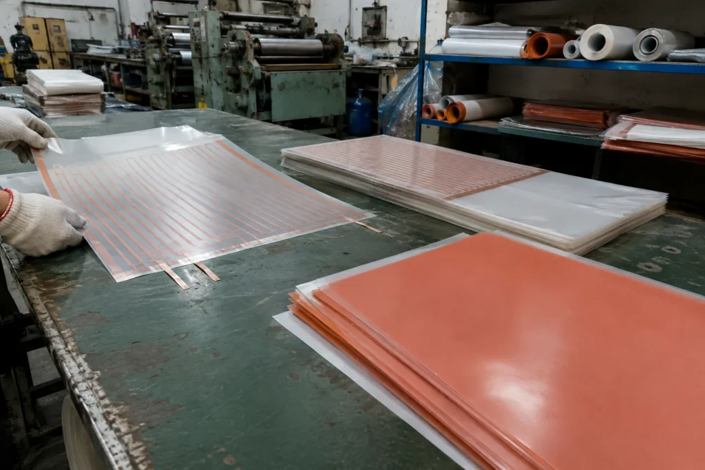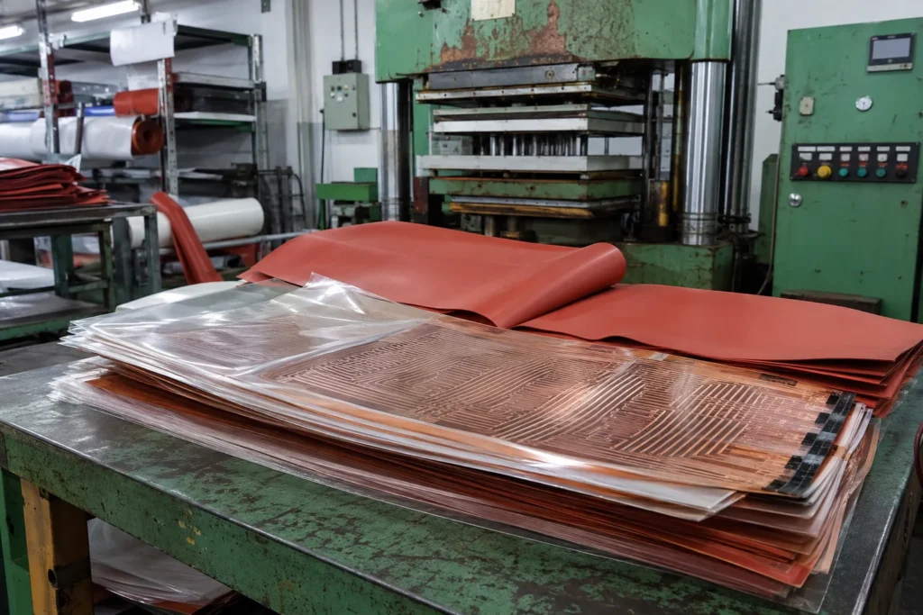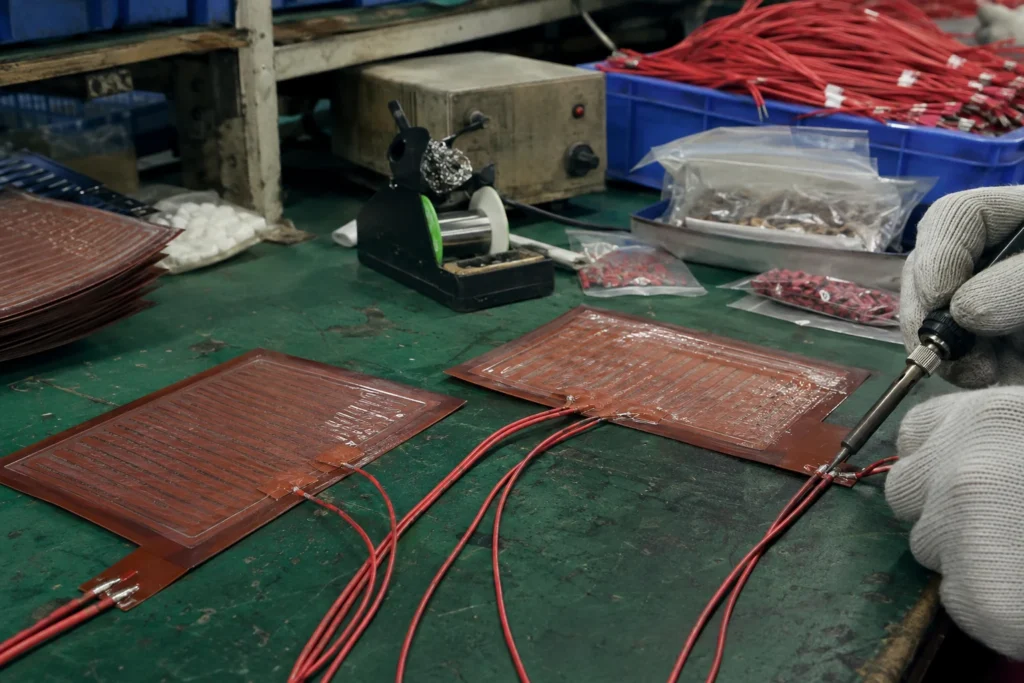
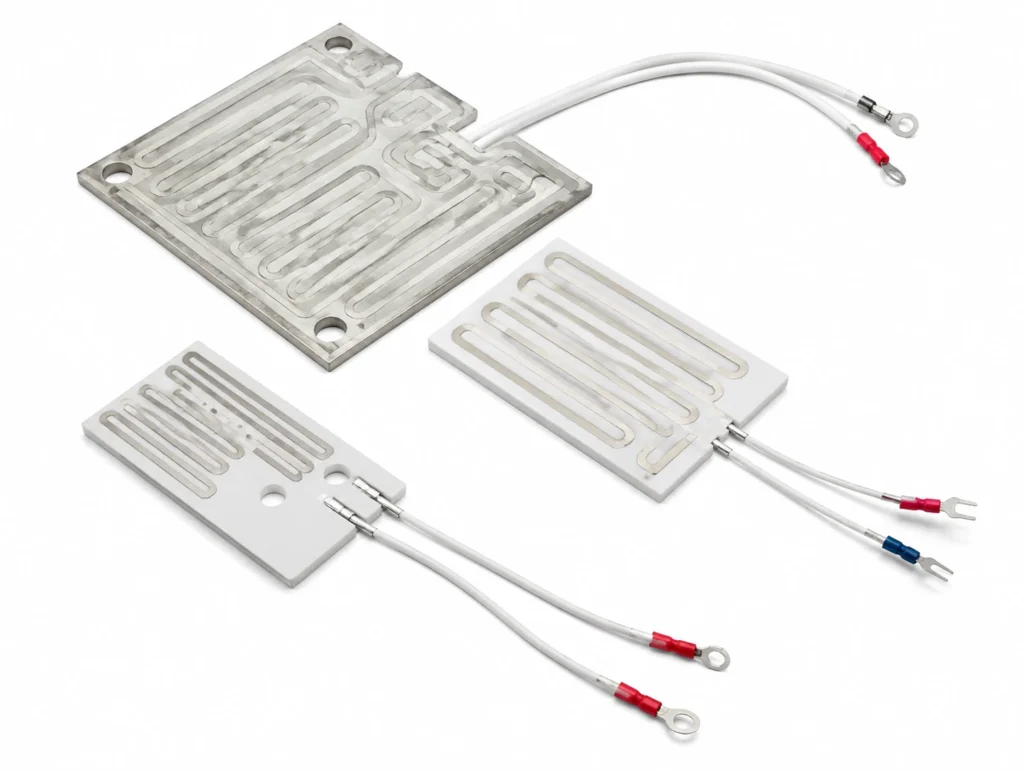
Low mass, fast, closely controlled plates for blood and infusion warming, dialysis and analyser reagent lines, built under an ISO 13485 system. Application guide for Medical Fluid Warming Thick Film Plates. The core duty of the construction is heating a metal or ceramic surface directly, with the resistor fired onto that surface, at watt densities and response times no attached heater can approach. A glass dielectric and a resistor paste are screen-printed onto 304 or 316 stainless, 96% alumina or anodised aluminium, fired, and then laser trimmed to resistance. There is no separate element and no interface to conduct across: the substrate is the heater, and in a flow application it is also the pressure boundary. The typical industries, the specification checklist, the control and protection requirements, installation practice and the exclusion cases are set out below. This construction is built up to 120 x 200 mm, 1.5 mm to 3 mm thick to your outline; the full capability table is further down the page. It is rated at 5 W/cm² in free air and 30 W/cm² bonded full-area to metal, and the difference between those two figures is the difference between a heater that lasts and one that does not.
Typical Applications for Medical Fluid Warming Thick Film Plates
The assemblies and sectors where this construction is specified:
- Industrial process plates: small precision platens and sealing bars where 400 °C is required and every polymer insulation is already out of the running.
- OEM equipment manufacture: designed-in heating on new equipment, specified from the surface, the target temperature and the available power at the design stage rather than retrofitted afterwards.
- Retrofit and equipment upgrades: replacing a failed or unsuitable heater on existing equipment, where the outline, the voltage and the mounting all have to match what is already there.
- Blood, infusion and dialysate warming: bringing a moving fluid to body temperature within a couple of degrees, where the low thermal mass is what makes the loop controllable and the overshoot small.
- Flow-through heating with no tank: coffee and beverage machines, dispensers, sanitary ware and medical fluid lines, where the water is heated as it passes and nothing is kept hot.
How to Specify Medical Fluid Warming Thick Film Plates for Your Application
- Outline drawing: There is no catalogue size to order from: this part is made to your outline. Send a drawing or a DXF showing the heated area, every hole and cutout, which face is bonded, and where the leads leave the part — the process builds up to 120 x 200 mm, 1.5 mm to 3 mm thick. Everything else on this list is quoted against that drawing.
- Overshoot, not just set point: A patient-facing warming plate is specified on what it does during a flow interruption as much as on what it does in steady state. State the maximum permissible fluid temperature, the flow range, and the independent means by which the plate is stopped when flow stops.
- Flow, rise and the no-flow case: Give the flow rate, the inlet temperature and the rise required, and then state explicitly what stops the heater when the flow does. Every flow-through module needs that answer before it is quoted, because the construction that makes it fast is the same one that makes a dry run destructive.
- Flow rate and temperature rise, not wattage: A flow-through module is specified by the litres per minute and the rise in degrees you need, together with the inlet temperature — that determines the power, and the power then has to be checked against the watt density the substrate can actually pass into the fluid. Quoting a wattage alone hides whichever of the three constraints is really binding.
- Dry-run and low-flow protection: This is the single most important line on a thick film order. With almost no thermal mass and a very high watt density, a module that keeps firing into an empty or stalled channel reaches destructive temperature in seconds, not minutes. Design in a fast sensor bonded to the substrate, a flow or level interlock, and a thermal cutoff that is independent of the controller.
- Substrate choice: Stainless is the wetted, pressure-bearing, mechanically robust option. Alumina goes higher in temperature, isolates the circuit electrically and is dimensionally excellent — and it is brittle, so it survives heat far better than it survives an uneven clamp. Anodised aluminium spreads heat fastest and stops well short of the other two on temperature.
- Sensor speed, not just accuracy: The thermal mass that would normally forgive a slow sensor is not there. Specify a thin-film RTD or a thermocouple bonded to the substrate itself; a bead thermistor in the air near the plate reads a temperature the plate passed through several seconds ago.
- Supply voltage: State the supply voltage: this construction is wound or printed for 24 V DC, 48 V DC, 110-120 V AC or 220-240 V AC, and it is built for the one voltage ordered rather than being switchable between them. At low voltage the current is the problem — a 120 W heater at 12 V draws 10 A, and the lead gauge, the connector and the switching device all have to carry it. At mains voltage the insulation, the earthing or double insulation and the creepage distances become part of the construction, and a low wattage at 230 V means a very fine, very long element that is harder to build reliably than its low-voltage equivalent.
- Wattage and watt density: This construction is rated at 5 W/cm² in free air and 30 W/cm² bonded full-area to metal. Those are not two options: they are the same heater under two cooling conditions, and the second figure is only true while the heat has somewhere to go. Design at the bonded figure and then leave the heater unbonded, air-gapped, or stuck to plastic or foam, and the element runs at roughly 6 times the density its own surface can shed — the insulation reaches its limit in minutes and the failure is permanent. Give the wattage you need and what the heater is bonded to in the same sentence, and the watt density can be checked against the construction before anything is built.
- Temperature limit: The continuous limit is 150 °C, and it belongs to fired glass dielectric on the substrate rather than to the element. Nichrome, Inconel and fired resistor pastes all survive far beyond it; what fails first is the material holding them, and no derating of the wattage moves that number. State the maximum temperature the assembly can reach under fault as well as the working set point, because it is the fault case that has to stay inside this number.
- Control and protection: This construction does not limit itself in any way. At rated voltage into a surface that has lost contact, run dry or lost its coolant, it goes on taking full power until the insulation fails, so a thermostat or a thermal cutoff sized to the assembly — not to the heater — belongs in the design and in the schematic. Where a fault must not be allowed to repeat itself, a one-shot thermal cutoff goes behind the resettable device, because a bimetal thermostat cycling on a genuine fault will cycle for as long as the power is on.
- Mounting: This construction is clamped rather than bonded, so the contact pressure, the flatness of the mating face and the thermal interface material are part of the electrical specification: they decide how much of the rated power actually reaches the load.
- Sensor and where it sits: A sensor can be built into the part rather than fitted next to it: NTC, PT100 or PT1000, a thermocouple, or a bimetal device. Say which, and mark its position on the drawing — a sensor under the densest part of the circuit, a sensor at the coldest corner and a sensor next to the load are three different control schemes, and the drawing is where that gets decided.
- Certification of the construction: The constructions behind this product are built and tested to UL 499, IEC/EN 60335, RoHS & REACH, CE Marking, ISO 13485. That is a statement about a construction — its insulation system, its creepage and clearances, its earthing, its marking and its tests — and not a claim that a particular made-to-drawing outline carries an approval of its own. Say at the enquiry which standard your end product is certified to, because it constrains the build rather than being added to it afterwards.
- Leads and termination: State the wire type, gauge, length and exit direction, and the termination — bare, ferrule, ring, spade or a specific connector housing. The lead exit is a mechanical design decision: it is where a flexible heater is most often folded during assembly, and the joint behind it cannot be inspected once the part is built.
Control, Protection and What Happens at a Fault
This construction does not limit itself in any way. At rated voltage into a surface that has lost contact, run dry or lost its coolant, it goes on taking full power until the insulation fails, so a thermostat or a thermal cutoff sized to the assembly — not to the heater — belongs in the design and in the schematic. Where a fault must not be allowed to repeat itself, a one-shot thermal cutoff goes behind the resettable device, because a bimetal thermostat cycling on a genuine fault will cycle for as long as the power is on.
- The control device: A sensor on the load and a controller — on/off where the load has thermal mass and a few degrees of swing is acceptable, PID where the set point has to be reached without overshoot. This is what holds the temperature; it is not what protects the assembly.
- The limit device: A bimetal thermostat or a thermal cutoff, sensing the heater or the hottest point of the assembly, wired so that it interrupts the heater regardless of what the controller is doing. It has to be independent of the control sensor: a broken sensor wire that the controller reads as cold is one of the commonest ways a heating assembly ends up at full power.
- The fault case to design against: Ask what happens if the heater loses contact with its load, if the fluid stops, if the fan stops, or if the controller output sticks on. In every one of those the heater goes on delivering full power into a surface that is no longer carrying it away, and the answer has to be a device that acts, not a calculation showing it would take a long time.
- Where the sensor goes: On the surface whose temperature is in the specification, in direct thermal contact with it. A sensor reading the air near a heated part reads a temperature that part passed through seconds earlier, and a loop closed on the lagging measurement overshoots the leading one every time it starts.
Clamping, Contact & Airflow Practice
- Clamp evenly across the fired face, through a compliant thermal interface where the mating part is not flat. Point loading a ceramic substrate cracks it, and a cracked substrate takes the fired circuit with it.
- Do not dent, bend or machine the substrate after firing. The dielectric and the resistor are a glass layer a few tens of microns thick; they tolerate temperature far better than they tolerate deflection.
- Bond or earth the substrate as the design requires and verify the isolation after assembly. On a stainless module the heated surface is also a wetted, conductive part of the appliance, and that is a safety path rather than a detail.
- Plan for scale in any water-side application. Fired resistor tracks pass their heat through the substrate into the fluid, and a scale layer on the wetted face is a thermal barrier the element cannot see — it raises the track temperature at unchanged power. State the water hardness so the watt density can be chosen with it in mind.
- Keep the fired face clean during assembly. Adhesive residue, marker ink and finger oils burn on at these surface temperatures and leave a permanent local hot spot.
Common Specification Mistakes with Medical Fluid Warming Thick Film Plates
- Relying on the controller alone for dry-run protection. The interlock and the cutoff have to work when the controller is the thing that failed.
- Sizing on average power and never analysing the interrupted-flow case. Almost every field failure of a flow-through thick film module is a control or plumbing fault, not a heater fault, and the heater is what gets destroyed by it.
- Using a slow sensor. Very low thermal mass means the loop has almost no natural damping — with a slow measurement the controller is always acting on old information, and the overshoot lands directly on the fired layer.
- Treating the maximum watt density as a design target. It is a limit that assumes ideal contact or ideal flow; the working design sits below it, and the margin is what absorbs scale, fouling and a partially blocked channel.
- Ignoring thermal shock. Quenching a hot ceramic substrate with cold water is a mechanical event, and repeating it is a fatigue test of the fired layers.
- Quoting only one of the two watt density figures in an internal specification. They differ by roughly 6 times on this construction, and a figure copied without the bonding condition attached to it is the single most reliable way to destroy one of these heaters.
- Designing to the working temperature and never checking the fault temperature against the 150 °C ceiling. This construction has less headroom than most of the alternatives, and it is the blocked, covered or dry case that uses it up.
Where Medical Fluid Warming Thick Film Plates Are Not the Right Choice
- Not flexible, in any form. The dielectric and the resistor are fired glass: they do not bend, and a substrate that flexes under clamping will craze them.
- Not made to an arbitrary curved outline. The construction wants a flat plate or a straight tube; a compound shape is a silicone or an epoxy duty.
- Not for untreated hard water without a scaling strategy. Scale is a barrier the element cannot sense and cannot compensate for, and it raises the track temperature at unchanged power until something gives.
- Not where the fault case is uncontrolled. A construction that can reach destructive temperature in seconds needs its protection designed in from the start rather than added after a failure.
- Not for a curved or irregular surface. This is a rigid construction and it heats what it is in contact with; a surface it can only touch in places is a surface it will heat in places.
- Not as its own protection. This construction has no self-limiting behaviour, so it is never the right answer for a design that has nowhere to put a thermostat or a thermal cutoff.
- Not above 150 °C continuous. That limit belongs to the insulation system rather than to the element, so it cannot be bought back by derating the wattage — above it, the construction itself has to change.