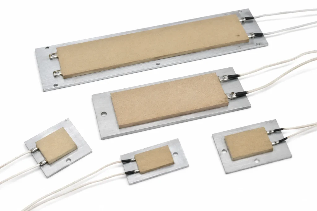
Aluminium Plate / Extrusion is chosen for constant temperature ptc heating plates before anything else about the part is decided. Spreads the heat before it reaches the load, which is what turns a line element into a uniform surface. The standard carrier for PTC assemblies and epoxy plates. The consequences — thickness, flexibility, what it survives and what it does not — follow below.
Aluminium Plate / Extrusion as an Insulation System
Spreads the heat before it reaches the load, which is what turns a line element into a uniform surface. The standard carrier for PTC assemblies and epoxy plates.
| Working range | To +200 °C with epoxy encapsulation; higher with silicone or ceramic bonding |
|---|---|
| Total thickness in this construction | Element 1.5 mm to 3 mm; assembly to your drawing |
| Dielectric withstand | 1800 V AC, 1 minute, element to case |
| Insulation resistance | greater than 100 Mu03a9 at 500 V DC |
| Maximum size, one piece | 30 x 30 mm to 150 x 200 mm |
The metal is not the insulation — it is the spreader. It turns a line element into a uniform surface, and it is why the assembly is uniform and slow rather than fast and patchy. The insulation limit belongs to whatever bonds the element to it.
The Temperature Ceiling, and What Sets It
Working range: To +200 °C with epoxy encapsulation; higher with silicone or ceramic bonding. The ceiling belongs to the insulation. Nichrome will run red; aluminium plate / extrusion will not, and it is the material around the element that decides what the part is rated at.
This construction is rated 120 °C continuous. That is a continuous figure at the element, not an ambient and not a surface temperature measured somewhere convenient — and it is not a figure that derating extends downwards from something higher. Past the ceiling the insulation degrades, the dielectric strength falls with it, and the failure is electrical rather than thermal.
The boundaries across this catalogue are all material boundaries: PET stops at 120 °C, filled epoxy at 150 °C, silicone rubber and polyimide at 200 °C, and above that only fired and inorganic systems — thick film on stainless or alumina, and mica — are candidates at all.
What Attacks Aluminium Plate / Extrusion
Adds thermal mass and therefore lag; not the choice where response time matters.
What a Constant Temperature PTC Heating Plates Is
Thin PTC assemblies for holding a fixed surface temperature — mirror demisting, sensor de-icing, condensation control — with no controller at all.
Barium titanate ceramic whose resistance rises steeply above its Curie point, so the power it draws falls as the surface approaches that temperature. The element cannot exceed the Curie point it was made to, whatever the supply or the control does. Bonded to an aluminium plate the ceramic is spread out into a uniform surface, and the plate is also what carries the heat away — an element clamped to nothing regulates itself down to almost no power at all.
The heat leaves through a clamped joint, and a clamped joint is only as good as the pressure and the flatness behind it. A thermal interface material or a thin film of thermal grease fills the gaps that machining leaves; without one, contact happens at the high spots and the element runs hotter than the plate it is bolted to.
| Element | barium titanate PTC ceramic |
|---|---|
| Insulation system | aluminium carrier with insulating film |
| Total thickness | Element 1.5 mm to 3 mm; assembly to your drawing |
| Maximum size, one piece | 30 x 30 mm to 150 x 200 mm |
| Continuous working temperature | 120 °C |
The continuous limit of 120 °C is set by aluminium carrier with insulating film. The element alloy would run far hotter; it is never the element that decides.
What the Insulation Changes About the Heater
The plate turns a line element into a surface. Uniformity across the heated face improves, hot spots over the element disappear, and the price is thermal mass: the same watts now have to heat the plate before they reach the load.
Attachment and Thermal Contact
The part is clamped, not bonded. What matters at the joint is flatness, contact pressure and a thermal interface material to fill what machining leaves behind — a dry joint between two nominally flat surfaces touches on perhaps a few percent of its area.
A PTC element clamped without a proper thermal path does not overheat — it throttles itself back and delivers a fraction of the power the assembly was specified for. The symptom of a bad joint here is a heater that seems underpowered rather than one that burns out.
The joint between the heated surface and the load carries every watt the element makes. Fill it: an interface pad, a thin film of thermal grease or a bonded assembly. Two dry surfaces bolted together are a thermal resistance, and that resistance appears as element temperature.
Watt Density: the Two Figures
This construction is rated at 0.3 W/cm² in free air and 2 W/cm² bonded over its whole area to metal. The second figure is 6.7 times the first, and the difference is not a safety margin — it is the heat sink. On a 100 x 150 mm outline, which is 150 cm², that is about 45 W hanging in air against about 3 W bonded down.
Specify at the figure that matches how the heater will actually run. A heater ordered at the bonded density and then switched on before it is attached — on the bench, during a test, after it has lifted off in service — reaches its insulation limit in minutes, because there is nowhere for the heat to go but through the insulation.
A PTC assembly behaves differently at the limit. Deprived of its heat sink it does not run away; it reduces its own power. The consequence of a poor thermal path here is a heater that delivers well under its nameplate power, not one that destroys itself.
Control and Protection
This is the one construction here that limits its own temperature. Above the Curie point the ceramic's resistance rises steeply, the current falls, and the element settles rather than climbing — so a PTC heater cannot thermally run away even with the control shorted out.
That is a safety property, not an accuracy one. Self-regulation holds a surface somewhere near the Curie point under whatever cooling it happens to have; it does not hold a set point, and the temperature it settles at moves with airflow, with supply voltage and with the load. Where a number has to be held, a sensor and a controller are still required.
Two things still have to be designed for: the inrush, which is several times the running current while the ceramic is cold and which the supply and any switching device must tolerate, and the electrical fault case, which self-regulation does nothing about — a fuse or a current-limited supply is still the protection against a short.
W
a
Where This Construction Is the Wrong Answer
- Do not plan on running above 120 °C. That ceiling belongs to the insulation system, not to the element alloy, and it is not a figure that derating extends — past it the insulation degrades and the dielectric strength goes with it.
- Do not use self-regulation as a substitute for temperature control where a set point matters, and do not present it as a substitute for a fuse. It bounds the temperature; it does not hold a value and it does nothing about a short circuit.
Leads and Terminations
Termination is specified on the drawing: lead length, gauge, insulation and the connector or tag at the end of it.
Connector and termination options: Faston 2.8/4.8 mm, crimp, or flying leads. A keyed housing removes a soldering operation from the customer's line and removes the possibility of the assembly being connected backwards; on a heater with a separate sensor circuit it also stops the sensor pair being mistaken for the power pair.
The lead exit is a thermal discontinuity as well as an electrical one. The joint between a fine element and a stranded lead is the hottest point of many heaters, so it is kept out of the highest watt density zone, strain relieved, and — where the exit sits in a hot area — insulated in PTFE rather than in silicone.
How to Specify One
This is a made-to-drawing part, so there is no catalogue number to quote. A quotation is built from the following, and the more of it that arrives with the enquiry the fewer rounds it takes:
- An outline drawing, or a sketch with dimensions: overall size, holes, cut-outs, radii and the lead exit position.
- The supply voltage, and whether it is AC or DC. The element is wound for one voltage; it is not a switchable range.
- The power required, or — better — the temperature to be reached and the mass or flow it has to be reached in. Given the second, the wattage can be calculated instead of guessed.
- What the heater is attached to, and how. This is what decides which watt density figure applies, and it is the question a quotation cannot proceed without.
- The ambient, and the lowest temperature the assembly must start from. A heater sized for a 20 °C start is undersized for a -30 °C one.
- Duty cycle: continuous, intermittent, or a warm-up to a deadline. Time to temperature is a specification, not a by-product.
- Sensor and protection: which sensor, where it goes, and which limit device is fitted in series with the element.
- The certification the end product is built to, named on the enquiry rather than after approval.
- Quantity and target price, because the construction that is right for fifty pieces is often not the one that is right for fifty thousand.
- The Curie point wanted, and the airflow or thermal path the assembly will have — both decide the power the element will actually deliver.
Lead time: Samples 7-10 days from approved drawing; production 15-20 days.
Constant Temperature PTC Heating Plates — Capability Table
These are process limits for the construction, not the specification of one stocked item. Every line is what the factory can hold; what your part holds is fixed on your drawing.
| Parameter | Specification | Limit / note |
|---|---|---|
| Construction | Barium titanate PTC ceramic, electroded on both faces, in an aluminium carrier | Assembly built around the element to suit the load |
| Curie temperature | +40 u00b0C to +120 u00b0C, selected | Selected at order u2014 it is the surface temperature ceiling and cannot be adjusted afterwards |
| Self-regulation | Power falls to a fraction of rated as the surface reaches the Curie point | No thermostat is required to prevent runaway; one may still be wanted for control |
| Element size | 30 x 30 mm to 150 x 200 mm | Standard element footprints; assemblies to your drawing |
| Supply voltage | 12 V, 24 V, 48 V | The same element works over a voltage band with different output |
| Power output | 0.3 W/cmu00b2 typical in still air, 2.0 W/cmu00b2 with forced air | Output is set by the airflow, not by a setting u2014 this is what self-regulating means |
| Inrush current | 3 to 8 times running current for 1 to 3 seconds | The supply and any relay or MOSFET must tolerate it |
| Dielectric strength | 1800 V AC, 1 minute, element to case | On the assembled unit with its insulation in place |
| Insulation resistance | greater than 100 Mu03a9 at 500 V DC | |
| Terminations | Faston 2.8/4.8 mm, crimp, or flying leads | Chosen for the assembly temperature |
| Life | Over 10,000 hours at rated conditions | Ageing shows as a slow rise in cold resistance, not as sudden failure |
| Certifications available | UL 499, IEC/EN 60335, RoHS, REACH, CE, IATF 16949 | Construction level |
| Control | None required u2014 the element is the control | Removes a controller, a sensor and a failure mode from the bill of materials |
Capability figures are for barium titanate PTC ceramic elements and the aluminium assemblies built around them. The defining property — that power falls steeply as the element approaches its Curie point, so surface temperature cannot run away — is inherent to the ceramic, not a feature of the control.