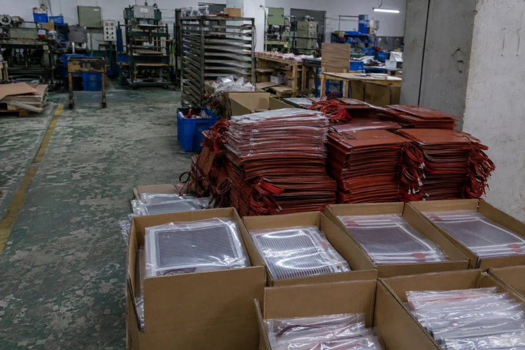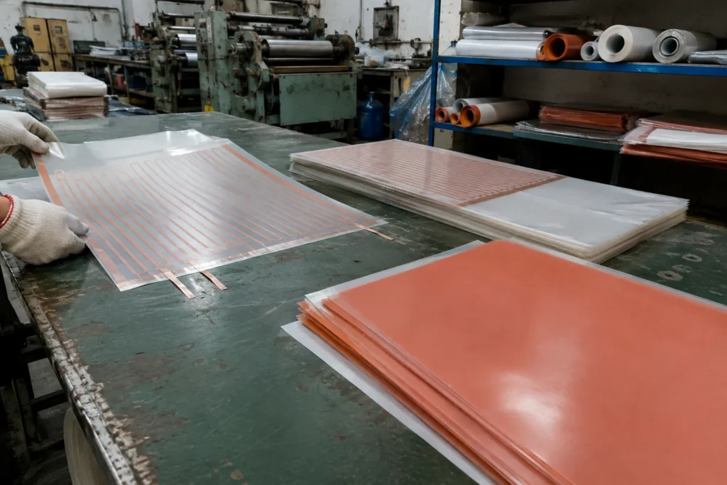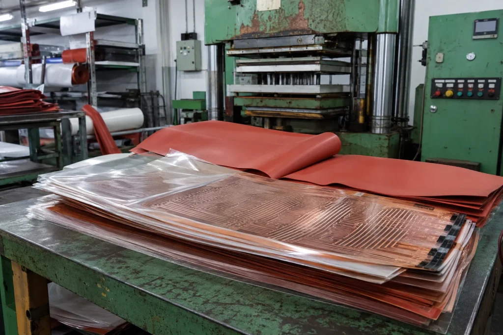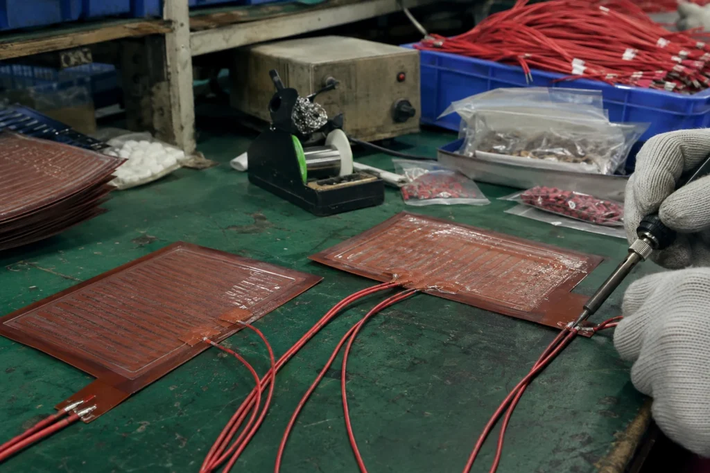
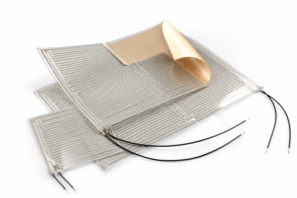
Thin PSA-backed film heaters bonded to the back of a mirror or a glass panel to clear condensation and light frost. Mirror and Glass Demisting Heaters are specified where a design calls for covering a large area at low watt density for the lowest cost per square metre of any construction here, anywhere the surface stays comfortably below 120 °C. Carbon or silver ink screen-printed onto 0.2 mm PET film in a roll-to-roll process, with printed or bonded busbars carrying the current in. It is cheap, thin and light — and it is limited by the film, which softens around 130 °C and loses its dielectric strength there. Below: typical end uses by industry, the specification checklist, the control and protection the construction requires, installation practice, and the applications it is not suited to. This construction is built up to 300 x 300 mm, 0.25 mm thick to your outline; the full capability table is further down the page. It is rated at 0.1 W/cm² in free air and 0.4 W/cm² bonded full-area to metal, and the difference between those two figures is the difference between a heater that lasts and one that does not.
Typical Applications for Mirror and Glass Demisting Heaters
The assemblies and sectors where this construction is specified:
- Pet mats and consumer warming products: high volume, low power, large area products where the bill of materials decides the design.
- Vending and refrigerated display equipment: door and glass heating to stop condensation forming where the customer has to see through it.
- OEM equipment manufacture: designed-in heating on new equipment, specified from the surface, the target temperature and the available power at the design stage rather than retrofitted afterwards.
- Retrofit and equipment upgrades: replacing a failed or unsuitable heater on existing equipment, where the outline, the voltage and the mounting all have to match what is already there.
- Vehicle interior and glass heating: seat cushions, backrests, mirrors and camera windows, terminated for a vehicle harness and built under an automotive quality system.
How to Specify Mirror and Glass Demisting Heaters for Your Application
- Outline drawing: There is no catalogue size to order from: this part is made to your outline. Send a drawing or a DXF showing the heated area, every hole and cutout, which face is bonded, and where the leads leave the part — the process builds up to 300 x 300 mm, 0.25 mm thick. Everything else on this list is quoted against that drawing.
- Clear aperture and optical edge: Bonded to the back of glass, the heater has to clear the viewed area or be uniform enough to be invisible through it. State the aperture, the outline and the bonded face, and remember the glass is the spreader — a film alone will show its own circuit as a demisting pattern.
- The covered case and the harness: A seat element runs under an occupant and a trim layer, which is the covered condition by definition — the watt density and the protective device are chosen for that, not for an open bench. State the connector, the wire gauge and the circuit protection on the vehicle side as part of the same specification.
- Carbon or silver: Printed carbon is the cheapest and covers area well, but its resistance tolerance is loose — plan for ±10 to 15% — and its watt density is low. Silver ink or etched copper on the same film holds a much tighter resistance, carries more current and gives better uniformity, at a higher cost per square metre. The choice is decided by the tolerance the circuit needs, not by the temperature.
- The covered and folded fault cases: A PET heater under a cushion, a blanket or a folded garment loses its ability to shed heat while the power stays constant. The film is at its limit by 120 °C, so state the worst realistic covering condition and design the watt density and the protective device around that case rather than the open one.
- Area, not wattage: This construction is specified by covering an area at a low density, and the total power follows. Asking for a high wattage on a small PET outline is asking for the one thing the film cannot do.
- Terminations and flex life: The busbar and the crimp or solder joint are where these heaters fail, not in the printed area. State how the part is terminated and where it will flex, and keep folds away from the busbar — a printed silver conductor cracks along a crease.
- Supply voltage: State the supply voltage: this construction is wound or printed for 12 V DC, 24 V DC, 110-120 V AC or 220-240 V AC, and it is built for the one voltage ordered rather than being switchable between them. At low voltage the current is the problem — a 120 W heater at 12 V draws 10 A, and the lead gauge, the connector and the switching device all have to carry it. At mains voltage the insulation, the earthing or double insulation and the creepage distances become part of the construction, and a low wattage at 230 V means a very fine, very long element that is harder to build reliably than its low-voltage equivalent.
- Wattage and watt density: This construction is rated at 0.1 W/cm² in free air and 0.4 W/cm² bonded full-area to metal. Those are not two options: they are the same heater under two cooling conditions, and the second figure is only true while the heat has somewhere to go. Design at the bonded figure and then leave the heater unbonded, air-gapped, or stuck to plastic or foam, and the element runs at roughly 4 times the density its own surface can shed — the insulation reaches its limit in minutes and the failure is permanent. Give the wattage you need and what the heater is bonded to in the same sentence, and the watt density can be checked against the construction before anything is built.
- Temperature limit: The continuous limit is 120 °C, and it belongs to PET polyester film rather than to the element. Nichrome, Inconel and fired resistor pastes all survive far beyond it; what fails first is the material holding them, and no derating of the wattage moves that number. State the maximum temperature the assembly can reach under fault as well as the working set point, because it is the fault case that has to stay inside this number.
- Control and protection: This construction does not limit itself in any way. At rated voltage into a surface that has lost contact, run dry or lost its coolant, it goes on taking full power until the insulation fails, so a thermostat or a thermal cutoff sized to the assembly — not to the heater — belongs in the design and in the schematic. Where a fault must not be allowed to repeat itself, a one-shot thermal cutoff goes behind the resettable device, because a bimetal thermostat cycling on a genuine fault will cycle for as long as the power is on.
- Attachment method: State how the heater is held against its surface: free (mechanically clamped or strapped), supplied with a pressure sensitive adhesive backing and a liner, or vulcanised or bonded to a part you send in. Adhesive is convenient and it is also a thermal layer and a temperature limit of its own, so it is a design decision rather than a packaging option.
- Sensor and where it sits: A sensor can be built into the part rather than fitted next to it: NTC, PT100 or PT1000, a thermocouple, or a bimetal device. Say which, and mark its position on the drawing — a sensor under the densest part of the circuit, a sensor at the coldest corner and a sensor next to the load are three different control schemes, and the drawing is where that gets decided.
- Certification of the construction: The constructions behind this product are built and tested to IEC/EN 60335, UL 94 V-0, RoHS & REACH, CE Marking, IATF 16949. That is a statement about a construction — its insulation system, its creepage and clearances, its earthing, its marking and its tests — and not a claim that a particular made-to-drawing outline carries an approval of its own. Say at the enquiry which standard your end product is certified to, because it constrains the build rather than being added to it afterwards.
- Leads and termination: State the wire type, gauge, length and exit direction, and the termination — bare, ferrule, ring, spade or a specific connector housing. The lead exit is a mechanical design decision: it is where a flexible heater is most often folded during assembly, and the joint behind it cannot be inspected once the part is built.
Control, Protection and What Happens at a Fault
This construction does not limit itself in any way. At rated voltage into a surface that has lost contact, run dry or lost its coolant, it goes on taking full power until the insulation fails, so a thermostat or a thermal cutoff sized to the assembly — not to the heater — belongs in the design and in the schematic. Where a fault must not be allowed to repeat itself, a one-shot thermal cutoff goes behind the resettable device, because a bimetal thermostat cycling on a genuine fault will cycle for as long as the power is on.
- The control device: A sensor on the load and a controller — on/off where the load has thermal mass and a few degrees of swing is acceptable, PID where the set point has to be reached without overshoot. This is what holds the temperature; it is not what protects the assembly.
- The limit device: A bimetal thermostat or a thermal cutoff, sensing the heater or the hottest point of the assembly, wired so that it interrupts the heater regardless of what the controller is doing. It has to be independent of the control sensor: a broken sensor wire that the controller reads as cold is one of the commonest ways a heating assembly ends up at full power.
- The fault case to design against: Ask what happens if the heater loses contact with its load, if the fluid stops, if the fan stops, or if the controller output sticks on. In every one of those the heater goes on delivering full power into a surface that is no longer carrying it away, and the answer has to be a device that acts, not a calculation showing it would take a long time.
- Where the sensor goes: On the surface whose temperature is in the specification, in direct thermal contact with it. A sensor reading the air near a heated part reads a temperature that part passed through seconds earlier, and a loop closed on the lagging measurement overshoots the leading one every time it starts.
Bonding & Installation Practice
- Bond to a clean, dry, low-energy-free surface. Wipe with isopropanol, apply from one edge with a roller and work the bubbles out; the film is thin enough that any trapped air is visible before it becomes a hot spot.
- Never crease the printed area, and never fold across a busbar. A printed conductor is a brittle layer on a flexible substrate: it tolerates bending to a radius and does not tolerate a fold.
- Support and strain-relieve the leads at the busbar. This joint carries the whole current of the heater into a printed layer, and it is the first thing to fail if it is allowed to move.
- Keep the heated area clear of anything insulating that was not in the thermal design — foam, upholstery layers, packaging — because that is what turns a comfortable 45 °C surface into a film at its limit.
- Where the part is assembled into fabric or upholstery, agree the facing and lamination with the heater rather than adding it afterwards; the facing changes the thermal behaviour of the element it covers.
Common Specification Mistakes with Mirror and Glass Demisting Heaters
- Specifying printed carbon where the design needs a tight resistance. Carbon ink is a ±10 to 15% process; if several elements have to match, or a controller infers power from resistance, that is a silver or an etched copper job.
- Sizing the watt density for the uncovered condition. Almost every PET application ends up covered by something in service, and the film has only 120 °C of headroom to absorb the difference.
- Leaving out the cutoff because the power is low. Low power over a large area still reaches the film limit when the heat cannot escape, and PET fails by softening and losing dielectric strength rather than by burning out visibly.
- Folding the element to fit a smaller opening during assembly. The crease is invisible for weeks and then becomes an open circuit or a hot spot.
- Quoting only one of the two watt density figures in an internal specification. They differ by roughly 4 times on this construction, and a figure copied without the bonding condition attached to it is the single most reliable way to destroy one of these heaters.
- Designing to the working temperature and never checking the fault temperature against the 120 °C ceiling. This construction has less headroom than most of the alternatives, and it is the blocked, covered or dry case that uses it up.
- Bonding a self-adhesive heater to an unprepared surface. A pressure sensitive adhesive bonds to what it can touch: machining oil, release agent, a rough finish or a cold surface all leave it with a fraction of its contact area, and the heater then runs partly unbonded while being powered as though it were fully bonded.
- Treating a mains-voltage flexible heater as an equivalent of the low-voltage version. It is a different construction: the insulation system, the creepage distances, the earthing arrangement and the element geometry all change, and the safety standard for the end product applies to the assembly it is fitted into.
Where Mirror and Glass Demisting Heaters Are Not the Right Choice
- Not above 120 °C continuous, under any conditions. PET softens around 130 °C and its dielectric strength goes with it, which makes it the wrong construction for anything that can dry out, be covered and overshoot.
- Not for high watt density. This is a construction for spreading a small amount of power over a large area; concentrated power belongs in polyimide, silicone or thick film.
- Not for oil, solvent or high-humidity immersion. The film and the printed inks are protected against handling, not against chemistry.
- Not where the part will be creased repeatedly. Repeated flexing at a fixed line cracks a printed conductor, and a cracked conductor concentrates current where it is still connected.
- Flexible is not the same as conformable. This construction wraps a cylinder cleanly and will not take a compound curve without wrinkling — for a doubly curved surface, silicone rubber is the construction that follows it.
- Not as its own protection. This construction has no self-limiting behaviour, so it is never the right answer for a design that has nowhere to put a thermostat or a thermal cutoff.
- Not above 120 °C continuous. That limit belongs to the insulation system rather than to the element, so it cannot be bought back by derating the wattage — above it, the construction itself has to change.