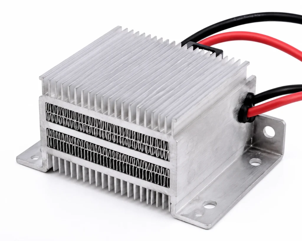
PTC elements bonded into an aluminium fin stack, for warming air in cabinets, dryers, vehicle cabins and enclosures. Finned PTC Air Heaters are used for warming air, a plate or a fluid with an element that physically cannot exceed its own Curie point, in duties where a control failure must not be allowed to become a runaway. Barium titanate ceramic whose resistance rises by orders of magnitude above its Curie point: as the element warms, it throttles its own current, so power falls as the surface approaches the design temperature. The ceramic is then bonded into an aluminium fin stack or onto a plate, which is what turns a small hot element into a useful heated surface. This page sets out the industries and assemblies where the construction is specified, what has to be stated on the drawing and the order, how it is installed, and the duties where a different construction is the right answer. This construction is built up to 50 x 50 mm to 250 x 150 mm frame, Element 1.5 mm to 3 mm; assembly to your drawing thick to your outline; the full capability table is further down the page. It is rated at 1 W/cm² in free air and 6 W/cm² bonded full-area to metal, and the difference between those two figures is the difference between a heater that lasts and one that does not.
Typical Applications for Finned PTC Air Heaters
The assemblies and sectors where this construction is specified:
- Mirror, sensor and camera de-icing: holding a fixed surface temperature on a mirror, a lidar or a camera window with no controller and no sensor in the loop at all.
- Fluid and coolant warming: washer fluid, coolant, urea and small water volumes, where the heater will inevitably be switched on with the reservoir empty at some point in its life.
- Incubators and laboratory enclosures: gentle, inherently limited air heating around samples that must never be cooked by a failed control.
- Cold-chain and vending equipment: condensation control and defrosting on doors, glass and drain lines in refrigerated cabinets.
- OEM equipment manufacture: designed-in heating on new equipment, specified from the surface, the target temperature and the available power at the design stage rather than retrofitted afterwards.
How to Specify Finned PTC Air Heaters for Your Application
- Footprint and rating: This is a component with a standard footprint rather than a made-to-drawing outline: it is ordered by its rating and its physical form, and the design work is in how it is mounted and what it is thermally connected to.
- The airflow is half the specification: A finned PTC assembly converts airflow into power. State the fan, the free area and the duct: the same core delivers a fraction of its rated power in still air, and that is the design behaving correctly rather than failing.
- Curie point, which is the specification: The Curie point is chosen from the standard range and it is what determines both the safety ceiling and the delivered power. It is not the surface temperature you will measure: the element sits above the surface it is heating, and the surface settles well below the Curie point according to how fast the air or the load carries heat away.
- Inrush current: A cold PTC element is a low resistance. At switch-on it draws several times its running current for a second or two, and the supply, the wiring, the fuse and the switching device all have to tolerate that surge — a relay or MOSFET chosen for the steady-state current will fail on the inrush, not in service.
- Airflow, for any finned assembly: A PTC air heater delivers whatever the airflow lets it deliver. State the fan, the duct and the air path with the heater; the same fin stack in a still cabinet and in a 2 m/s duct are two different power figures, and neither is a fault.
- Supply voltage: State the supply voltage: this construction is wound or printed for 12 V DC, 24 V DC, 110-120 V AC or 220-240 V AC, and it is built for the one voltage ordered rather than being switchable between them. At low voltage the current is the problem — a 120 W heater at 12 V draws 10 A, and the lead gauge, the connector and the switching device all have to carry it. At mains voltage the insulation, the earthing or double insulation and the creepage distances become part of the construction, and a low wattage at 230 V means a very fine, very long element that is harder to build reliably than its low-voltage equivalent.
- Wattage and watt density: This construction is rated at 1 W/cm² in free air and 6 W/cm² bonded full-area to metal. Those are not two options: they are the same heater under two cooling conditions, and the second figure is only true while the heat has somewhere to go. Design at the bonded figure and then leave the heater unbonded, air-gapped, or stuck to plastic or foam, and the element runs at roughly 6 times the density its own surface can shed — the insulation reaches its limit in minutes and the failure is permanent. Give the wattage you need and what the heater is bonded to in the same sentence, and the watt density can be checked against the construction before anything is built.
- Temperature limit: The continuous limit is 250 °C, and it belongs to aluminium carrier with insulating film rather than to the element. Nichrome, Inconel and fired resistor pastes all survive far beyond it; what fails first is the material holding them, and no derating of the wattage moves that number. State the maximum temperature the assembly can reach under fault as well as the working set point, because it is the fault case that has to stay inside this number.
- Control and protection: A PTC element cannot exceed its own Curie point: as the ceramic warms, its resistance climbs steeply and the power it draws collapses, so a failed control, a blocked airflow or a dry run ends in a warm element rather than a fire. That is over-temperature protection, and it is not temperature control — the surface settles wherever the load and the airflow put it, several tens of degrees below the Curie point, and a duty that has to hold a set point to a few degrees still needs a sensor and a controller. The circuit also has to survive the cold inrush, which is several times the running current for the first second or two.
- Mounting: This construction is clamped rather than bonded, so the contact pressure, the flatness of the mating face and the thermal interface material are part of the electrical specification: they decide how much of the rated power actually reaches the load.
- Certification of the construction: The constructions behind this product are built and tested to UL 499, IEC/EN 60335, RoHS & REACH, CE Marking, IATF 16949. That is a statement about a construction — its insulation system, its creepage and clearances, its earthing, its marking and its tests — and not a claim that a particular made-to-drawing outline carries an approval of its own. Say at the enquiry which standard your end product is certified to, because it constrains the build rather than being added to it afterwards.
- Leads and termination: State the wire type, gauge, length and exit direction, and the termination — bare, ferrule, ring, spade or a specific connector housing. The lead exit is a mechanical design decision: it is where a flexible heater is most often folded during assembly, and the joint behind it cannot be inspected once the part is built.
Control, Protection and What Happens at a Fault
A PTC element cannot exceed its own Curie point: as the ceramic warms, its resistance climbs steeply and the power it draws collapses, so a failed control, a blocked airflow or a dry run ends in a warm element rather than a fire. That is over-temperature protection, and it is not temperature control — the surface settles wherever the load and the airflow put it, several tens of degrees below the Curie point, and a duty that has to hold a set point to a few degrees still needs a sensor and a controller. The circuit also has to survive the cold inrush, which is several times the running current for the first second or two.
- What self-regulation covers: The runaway case. Resistance climbs steeply above the Curie point, so a blocked airflow, a dry run or a control failure ends with the element throttled back to a fraction of its power. No thermostat is needed to prevent an over-temperature.
- What it does not cover: Accuracy. The surface temperature is whatever the load and the airflow leave you with, well below the Curie point, and it moves as conditions change. A duty specified as a number with a tolerance needs a sensor on the load and a controller in the loop, exactly as a resistive heater would.
- What still has to be in the circuit: Normal electrical protection, sized for the cold inrush rather than the running current, and — where the system has to notice a failure rather than merely survive it — a means of detecting that the heater has throttled itself, since a PTC assembly that has stopped delivering looks exactly like one that is switched off.
Clamping, Contact & Airflow Practice
- Give a finned assembly its designed air path and keep it clear. A blocked PTC heater does not burn out — it simply stops delivering, and the symptom is a cold cabinet rather than an alarm, so it is worth designing an airflow or current check into the system.
- Clamp a plate assembly evenly against the load with a thermal interface material. The self-regulating behaviour depends on the element being able to shed heat; a poor contact patch reduces the delivered power long before it endangers anything.
- Size the supply and the switching device for the cold inrush, not for the running current, and choose a fuse with the surge tolerance to match.
- Mount the element so the ceramic is not stressed. It is a brittle disc or bar with electroded faces; the aluminium assembly is what takes the mechanical load.
- Keep the connections accessible and correctly rated. Terminal heat rise is a real failure mode on assemblies that run for years unattended in an outdoor cabinet.
Common Specification Mistakes with Finned PTC Air Heaters
- Treating self-regulating as self-controlling. A PTC heater will not run away, and that is all it promises: it does not hold a set point, and a duty that needs the surface within a few degrees still needs a sensor and a controller around it.
- Sizing the power supply for the steady-state power. The inrush is several times higher, and it is the number the supply and the switching device have to survive.
- Assuming the surface will reach the Curie point. It never does — the Curie point is the ceiling of the ceramic, and the useful surface temperature is whatever the load and the airflow leave you with, tens of degrees lower.
- Specifying a PTC element and then blocking the fins for packaging reasons. The construction converts airflow into power; take the airflow away and you have taken the power away.
- Quoting only one of the two watt density figures in an internal specification. They differ by roughly 6 times on this construction, and a figure copied without the bonding condition attached to it is the single most reliable way to destroy one of these heaters.
Where Finned PTC Air Heaters Are Not the Right Choice
- Not for accurate temperature control. Where the specification is a set point with a tolerance, a fixed-resistance heater with a sensor and a controller is the right answer, and the PTC element is an inherently safe alternative to that loop rather than a better version of it.
- Not made to an arbitrary outline. The element sizes are standard footprints and the assembly is built around them, so a design that needs an outline drawn to a surface belongs in silicone, polyimide or epoxy.
- Not where the delivered power must be constant regardless of temperature. Power falls as the element warms, by design; that curve is the whole point of the construction and it cannot be tuned out.
- Not where high power is needed from a very small package. Power density is limited by the element and by what the assembly can shed, and stacking Curie point to force more power out defeats the safety argument that justified the choice.
- Not for a curved or irregular surface. This is a rigid construction and it heats what it is in contact with; a surface it can only touch in places is a surface it will heat in places.
- Not where the surface temperature is a specified number with a tolerance on it. Self-regulation is a ceiling, not a set point, and the delivered temperature moves with the load and the airflow.
- Not made to an arbitrary outline. This is a standard-footprint component that an assembly is designed around; where the heated area has to follow a drawn shape, a made-to-drawing construction is the right starting point.