Silicone Rubber Heaters · Heaters with Sensors & Controls
Silicone Heaters with Integrated Thermostat
Continuous to 200 °C, wound for 5-220 V, built to UL 499 / IEC 60335 / RoHS. Set the outline, the voltage and the wattage on the drawing below and it redraws to them.
Silicone Heaters with Integrated Thermostat are continuous to 200 °C, wound for 5-220 V, watt density 0.8 W/cm² in free air and 5 W/cm² bonded to a heat sink, about 1.5 mm thick. The outline is cut to your drawing, up to 500 x 1000 mm (one piece) in one piece. It does not limit its own temperature: a thermostat, a thermal cutoff or a control loop with an independent over-temperature channel belongs in the design.
Continuous temperature
to 200 °C
Supply voltage
5-220 V
Watt density
0.8 W/cm² free air / 5 W/cm² bonded
Thickness
1.5 mm
Maximum one-piece size
500 x 1000 mm (one piece)
These are the process limits for this construction, not the rating of a finished part. The ratings of your heater come from the drawing it is built to, and the watt density it can carry depends on what it is bonded to.
Silicone Heaters with Integrated Thermostat — UL 499 / IEC 60335 / RoHS
Set the outline, the size, the voltage and the power you have in mind. The drawing
redraws to match, and the panel works out the heated area, the watt density and the current — then checks
that watt density against what this construction survives in free air and bonded to a heat sink. Those two
limits are different by several times, and it is the difference that decides whether a heater lasts.
Fills in the form below; attach your outline drawing or DXF there.
Build the Drawing
The panel above checks whether a size and a wattage can be built. This is the drawing itself: set the outline, route the heating track, place the lead wires, terminals, connector and temperature sensor, working in silicone rubber, and turn the model to look at it. When it is right, export the 2D drawing as a PDF or a DXF and send it with your enquiry — a drawing is what a quotation for silicone heaters with integrated thermostat is actually written from.
HEATING FILMDRAWING
Silicone Rubber Heater
Draw the outline, route the heating track, place the lead exits, terminals and sensor, dimension it, then export a PDF or a DXF and send it with your enquiry. Nothing here is a stock part and nothing you draw commits you to anything.
CMD
Want to compare constructions before you draw?
Open the full builder, where every film family is selectable in one place.
Request a Quotation for Silicone Heaters with Integrated Thermostat
The form below follows the current technical drawing configuration. Change the drawing values above and the request details update automatically.
Fitted under the same insulation and tested as one assembly
Certifications available
UL 499 construction, IEC/EN 60335, UL 94 V-0 materials, RoHS, REACH, CE
Constructions are built to these; the certificate covers the construction, not every outline
Thermostat
KSD9700 bimetal, 40 u00b0C to 150 u00b0C open point, u00b15 u00b0C
Self-resetting; a one-shot thermal fuse is fitted where reset must not happen
Wiring
Thermostat in series with the element, or on separate leads
In series is fail-safe and gives you no diagnostic; separate leads give the opposite
Silicone Heaters with Integrated Thermostat are silicone rubber heaters built to your drawing. This page is the process capability behind them — the sizes that can be pressed, the watt density the construction survives, the temperature the insulation tolerates, the voltages it is wound for — followed by how it is attached, how it is protected, and what a quotation needs from you.
What Are Silicone Heaters with Integrated Thermostat?
Silicone Heaters with Integrated Thermostat are silicone rubber heaters. They are specified by supply voltage and outline together with the outline drawing, the wattage or the temperature to be held, and what the heater is bonded to — that last one decides the permissible watt density and is the question a quotation cannot skip. The construction is built and tested to UL 499 / IEC 60335 / RoHS.
Construction & Insulation System
The insulation is fibreglass-reinforced silicone rubber on both faces, vulcanised around a nichrome wire element or an etched Inconel foil circuit. That insulation is what sets the temperature limit — 200 °C continuously, 240 °C briefly — not the element, which would tolerate far more. Silicone is conformable, tear resistant and unaffected by moisture and ozone, but it is permeable to water vapour and is attacked by concentrated acids and some solvents, so it is not a barrier layer. Wire is the lower-tooling-cost construction and suits simple outlines; etched foil spreads heat more evenly, allows a higher watt density and can vary the wattage zone by zone across one part.
Watt Density
In free air, with nothing conducting heat away from it, this construction carries 0.8 W/cm². Bonded over its full area to metal that carries the heat off, it carries 5 W/cm². The second figure is not an upgrade of the first — it is a different operating condition, and a heater ordered at 5 W/cm² and then run unbonded fails within minutes. Divide the wattage you need by the area you have before anything else: if the answer is above the free-air figure, either the area grows or the heater gets bonded down.
Typical Applications
Lithium battery packs held above their charging floor in the cold, pipes and drums kept from freezing or kept pumpable, press platens and laminating beds, incubators and warming cabinets, enclosures kept above dew point — anywhere a controlled watt density has to go onto a curved or irregular surface between -50 °C and +200 °C. Read the full application guide for Silicone Heaters with Integrated Thermostat →
Specifying the Silicone Heaters with Integrated Thermostat
Most enquiries start from the supply that is already in the machine rather than from a construction. The voltage pages take one supply at a time — 5 V DC, 12 V DC and 24 V DC — and set out what the element is wound for at that voltage, the current the leads and the switch have to carry, and where the wattage has to be split across more than one circuit.
The insulation system, not the element, decides how hot this can run and whether it can be bent at all: Fibreglass-Reinforced Silicone Rubber and Aramid Paper (Nomex type). Each page states the continuous ceiling that material sets, the dielectric withstand it gives, and what choosing it costs in flexibility or in thickness.
The duty temperature is the figure that rules constructions out rather than ranking them, so it is worth settling early: 120 °C to 150 °C and 150 °C to 200 °C. Each page states what survives that band continuously, and what the margin between the surface temperature and the insulation limit needs to be.
This construction is built and tested to RoHS & REACH and CE Marking — worth checking against the standard your own end product is certified under, because a part built to one scope does not automatically satisfy another. For the equipment and duties this construction is actually specified for, see where silicone heaters with integrated thermostat are used.
Silicone Heaters with Integrated Thermostat — UL 499 / IEC 60335 / RoHS
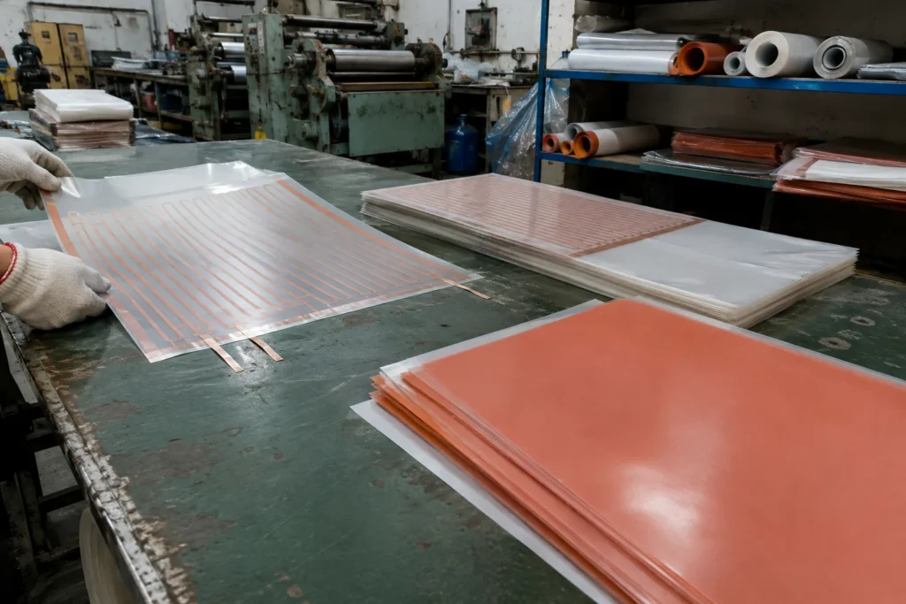
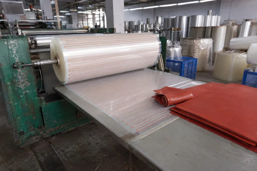
This heater is laid out, wound or etched, laminated, cut, tested and imaged in-house. The stages below are where its resistance tolerance, its temperature uniformity and its insulation integrity are actually decided.
01
Circuit design & material preparation
The customer outline comes in as a drawing or a DXF, and the element is laid out inside it: conductor gauge from the voltage, path length from the resistance, pitch from the watt density wanted at each part of the surface. Where the load needs more heat at the edges than in the middle, that is decided here, in the geometry, not later with more power. The insulation, the foil or wire and the adhesive for that build are then drawn from stock and staged together as one kit.
Calculated resistance and watt density checked against the construction limits before any tooling is cut; every material lot recorded against the works order.
02
Roll feeding & sheet handling
Film and silicone sheet are fed from the roll and cut to sheet, handled flat and kept clean. A fingerprint, a crease or a speck of dust trapped under the insulation becomes a void after pressing, and a void is a place the heat cannot leave from.
Sheet cleanliness and flatness checked at feed; material lot number stays with the sheet through to the finished part.
03
Element preparation & lay-up
Wire-wound elements are wound on a glass carrier at the calculated pitch; etched-foil circuits are photo-imaged and etched from Inconel or copper foil to a trace width held within 0.05 mm. That tolerance is what makes the resistance repeatable from lot to lot, which is what makes the temperature repeatable. The element and its sensor are then stacked between the insulation sheets in the order the drawing specifies.
Trace width and element resistance measured before lamination — a circuit out of tolerance is scrapped here, not after it is sealed inside the part.
04
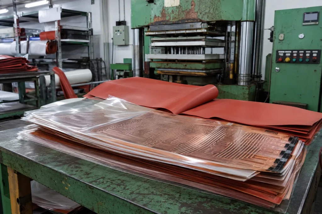
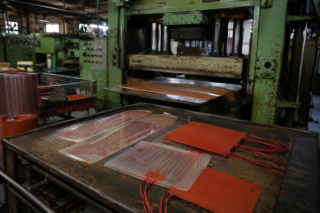
Lamination & vulcanising
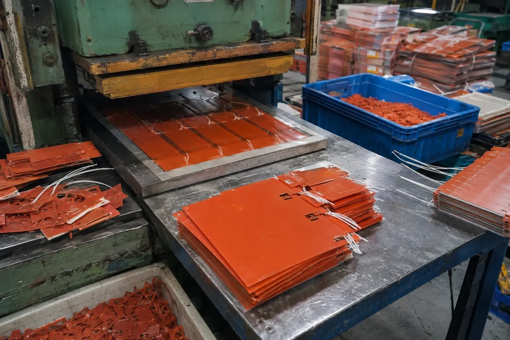
The lay-up is pressed under heat: silicone is vulcanised, polyimide and PET are laminated with a high temperature adhesive, epoxy plates are potted under vacuum so no voids are left anywhere in the heat path. A void is not a cosmetic defect — it is a place the heat cannot leave from, and it becomes the hot spot that ends the part.
Press temperature, pressure and dwell recorded per lot; potted plates checked for voids.
05
Die cutting
The outline is die cut with radiused corners — a die does not cut a sharp inside corner, and a sharp corner in a film is where a tear starts. Cut-outs, sensor windows and mounting holes come out in the same operation, which is why they have to be on the drawing before the tool is made rather than added afterwards.
Outline to ±0.5 mm on film, ±1.5 mm on silicone, gauged against the first-off sample for the tool.
06
Leads, terminals & connectors
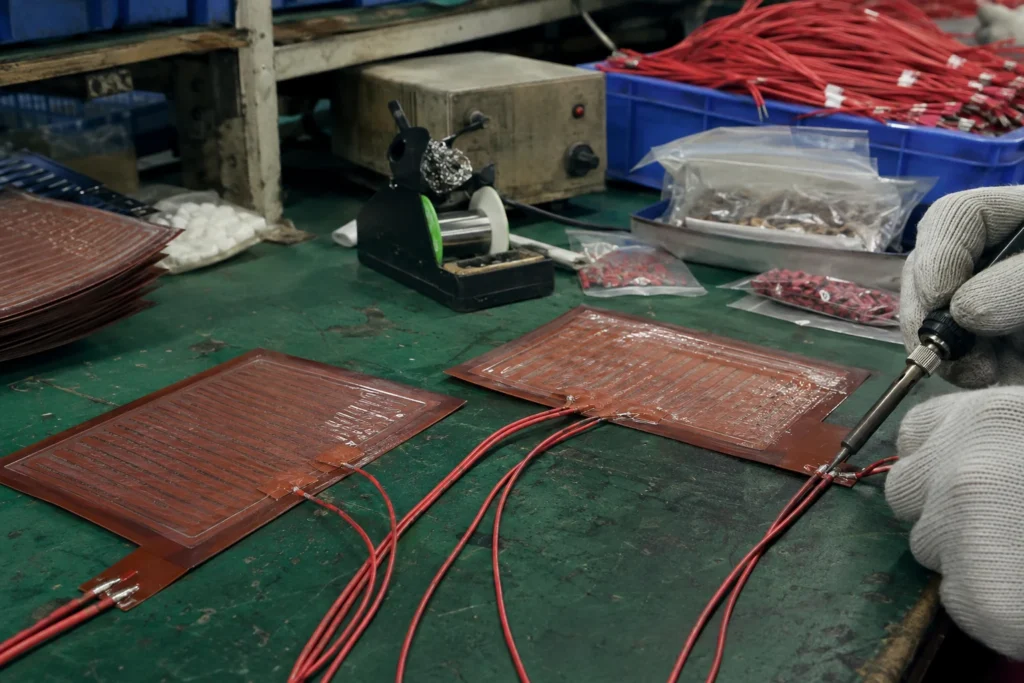
Leads are crimped or soldered at the exit and strain relieved, then connectors are fitted to the harness drawing so the assembly line never has to solder. The lead is worth as much attention as the heater: its jacket rating is frequently the lowest temperature limit in the whole assembly, and the exit is where a flexible heater is handled and where it fails if the relief is wrong.
Lead pull-out tested per lot; jacket rating and connector part number checked against the drawing rather than against the last order.
Video: Silicone Heaters with Integrated Thermostat
Third-party video, selected automatically for this topic. It is not produced by Heating Film and is not a specification source — use the tables on this page for dimensional data.
Frequently Asked Questions
What sizes do Silicone Heaters with Integrated Thermostat come in?
There is no size list. Silicone Heaters with Integrated Thermostat are cut to your outline, so the size is whatever your drawing says, up to 500 x 1000 mm. Larger areas are built as separate zones with their own circuits. Send a dimensioned drawing or a DXF and the quotation comes back against that outline.
How much power can Silicone Heaters with Integrated Thermostat take?
Two figures, and they are not interchangeable. In free air, with nothing conducting heat away, 0.8 W/cm². Bonded over its full area to metal that carries the heat off, 5 W/cm². A heater ordered at the second figure and then run in the first condition fails within minutes, so the quotation asks what the heater is bonded to before it asks anything else.
How hot can Silicone Heaters with Integrated Thermostat run?
200 °C continuously. That limit belongs to the insulation system — Fibreglass-Reinforced Silicone Rubber or Aramid Paper (Nomex type) — not to the element, which would tolerate a good deal more. It is a hard ceiling: above it the insulation degrades, and no derating scheme buys headroom. Past 200 °C the construction has to change rather than be pushed.
What protects Silicone Heaters with Integrated Thermostat from overheating?
Nothing in the heater itself — a heater is a resistor and has no opinion about temperature. The protection is a separate part of the design, and on this construction it is normally a bimetal thermostat or a one-shot thermal cutoff fitted inside the insulation, in series with the element. It can be built into the heater at manufacture, which is both cheaper and more reliable than adding it to the assembly afterwards, and it is a different component from the sensor that closes the control loop: the case the cutoff exists for is the loop failing on.
How are Silicone Heaters with Integrated Thermostat fitted?
They are bonded with a factory-applied pressure sensitive adhesive to a degreased, smooth surface, rolled on from one edge so no air is trapped; an air pocket under a bonded heater is a hot spot and it is permanent.
What voltages are Silicone Heaters with Integrated Thermostat available in?
5 V DC, 12 V DC, 24 V DC, 36 V DC, 48 V DC, 110-120 V AC and 220-240 V AC. The element is wound for the voltage ordered — it is not a switchable range, and running a heater at a voltage other than the one it was wound for changes its power by the square of the ratio. Resistance is held to u00b11.5 mm on dimensions up to 300 mm, u00b10.5%% above.
What is the dielectric strength of Silicone Heaters with Integrated Thermostat?
2500 V AC, 1 minute, with insulation resistance above 100 MΩ at 500 V DC measured after the dielectric test. Both are tested on every unit rather than on a sample, because a heater that fails this test in service fails it into whatever it is bonded to.
How do I get a quotation?
Set the outline, size, voltage and power in the builder on this page and send that configuration through, or attach a drawing. The quotation needs six things: the outline, the supply voltage, the power or the temperature you need to hold, what the heater is bonded to, the ambient it works in, and the quantity. With those, a quotation comes back within one business day.
Need a heater quoted?Message our engineers on WhatsApp — send an outline drawing and the supply voltage and get pricing back fast.Start WhatsApp Chat →
This website uses only necessary and functional cookies to operate, secure, and improve basic website performance.
We do not use advertising cookies, Google Analytics, or cross-site tracking technologies.